ZHCSHT3B December 2017 – October 2019 INA381
PRODUCTION DATA.
- 1 特性
- 2 应用
- 3 说明
- 4 修订历史记录
- 5 Pin Configuration and Functions
- 6 Specifications
- 7 Detailed Description
- 8 Applications and Implementation
- 9 Power Supply Recommendations
- 10Layout
- 11器件和文档支持
- 12机械、封装和可订购信息
封装选项
请参考 PDF 数据表获取器件具体的封装图。
机械数据 (封装 | 引脚)
- DGS|10
- DSG|8
散热焊盘机械数据 (封装 | 引脚)
- DSG|8
订购信息
7.4.1.2 Latch Output Mode
Some applications cannot continuously monitor the state of the output ALERT pin to detect an overcurrent condition, as described in the Transparent Output Mode section. A typical example of this type of application is a system that only periodically polls the ALERT pin state to determine if the system is functioning correctly. If the device is set to transparent mode in this type of application, the state change of the ALERT pin can be missed when ALERT is pulled low if the out-of-range condition does not appear during one of these periodic polling events. Latch output mode is specifically intended to accommodate these applications.
As shown in Table 1, the device is placed into the corresponding output mode based on the signal connected to RESET. The difference between latch mode and transparent mode is how the alert output responds when an overcurrent event ends. In transparent mode (RESET = low), when the differential input signal drops below the limit threshold level after the ALERT pin asserts because of an overcurrent event, the state of the ALERT pin returns to the default high setting to indicate that the overcurrent event is complete.
Table 1. Output Mode Settings
| OUTPUT MODE | RESET PIN SETTING |
|---|---|
| Transparent | RESET = low |
| Latch | RESET = high |
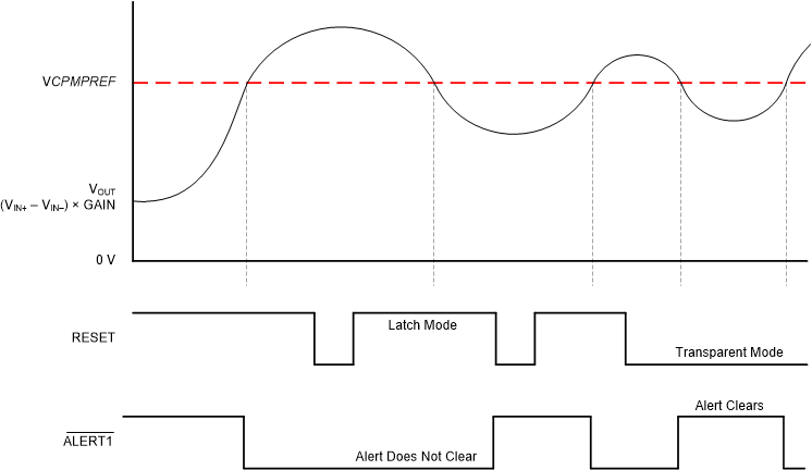
In latch mode (RESET = high), when an overlimit condition is detected and the ALERT pin is pulled low, the ALERT pin does not return to the default high state when the differential input signal drops to less than the alert threshold level. To clear the alert, the RESET pin must be pulled low for at least 100 ns. If the differential input signal is less than the alert threshold, pull the RESET pin low to return ALERT to the default high level. If the input signal exceeds the threshold limit when the RESET pin is pulled low, the ALERT pin remains low. When the alert condition is detected by the system controller, set the RESET pin back to high to place the device back in latch mode.
Figure 45 shows the latch and transparent modes. In Figure 45, when VIN drops to less than the VLIMIT threshold for the first time, the RESET pin pulls high. With the RESET pin pulled high, the device is set to latch mode so that the alert output state does not return high when the input signal drops to less than the VLIMIT threshold. Only when the RESET pin is pulled low does the ALERT pin return to the default high level, thus indicating that the input signal is below the limit threshold. When the input signal drops to less than the limit threshold for the second time, the RESET pin is already pulled low. The device is set to transparent mode at this point, and the ALERT pin is pulled back high when the input signal drops below the alert threshold.
 Figure 45. Transparent Mode Versus Latch Mode