ZHCSFQ7E November 2016 – December 2024 ISO7710
PRODUCTION DATA
- 1
- 1 特性
- 2 应用
- 3 说明
- 4 Pin Configuration and Functions
-
5 Specifications
- 5.1 Absolute Maximum Ratings
- 5.2 ESD Ratings
- 5.3 Recommended Operating Conditions
- 5.4 Thermal Information
- 5.5 Power Ratings
- 5.6 Insulation Specifications
- 5.7 Safety-Related Certifications
- 5.8 Safety Limiting Values
- 5.9 Electrical Characteristics—5-V Supply
- 5.10 Supply Current Characteristics—5-V Supply
- 5.11 Electrical Characteristics—3.3-V Supply
- 5.12 Supply Current Characteristics—3.3-V Supply
- 5.13 Electrical Characteristics—2.5-V Supply
- 5.14 Supply Current Characteristics—2.5-V Supply
- 5.15 Switching Characteristics—5-V Supply
- 5.16 Switching Characteristics—3.3-V Supply
- 5.17 Switching Characteristics—2.5-V Supply
- 5.18 Insulation Characteristics Curves
- 5.19 Typical Characteristics
- 6 Parameter Measurement Information
- 7 Detailed Description
- 8 Application and Implementation
- 9 Device and Documentation Support
- 10Revision History
- 11Mechanical, Packaging, and Orderable Information
封装选项
请参考 PDF 数据表获取器件具体的封装图。
机械数据 (封装 | 引脚)
- D|8
- DW|16
散热焊盘机械数据 (封装 | 引脚)
订购信息
8.2.3.1 Insulation Lifetime
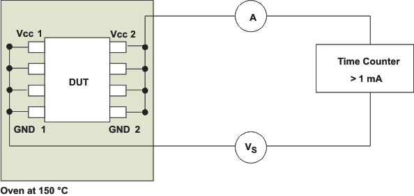
Insulation lifetime projection data is collected by using industry-standard Time Dependent Dielectric Breakdown (TDDB) test method. In this test, all pins on each side of the barrier are tied together creating a two-terminal device and high voltage applied between the two sides; See Figure 8-4 for TDDB test setup. The insulation breakdown data is collected at various high voltages switching at 60 Hz over temperature. For reinforced insulation, VDE standard requires the use of TDDB projection line with failure rate of less than 1 part per million (ppm). Even though the expected minimum insulation lifetime is 20 years at the specified working isolation voltage, VDE reinforced certification requires additional safety margin of 20% for working voltage and 50% for lifetime which translates into minimum required insulation lifetime of 30 years at a working voltage that's 20% higher than the specified value.
Figure 8-5 shows the intrinsic capability of the isolation barrier to withstand high voltage stress over the lifetime of the device. Based on the TDDB data, the intrinsic capability of the insulation is 1500 VRMS with a lifetime of 36 years. Other factors, such as package size, pollution degree, material group, and more can further limit the working voltage of the component. The working voltage of DW-16 package is specified up to 1500 VRMS and D-8 package up to 450 VRMS. At the lower working voltages, the corresponding insulation lifetime is much longer than 36 years.
 Figure 8-4 Test Setup for Insulation Lifetime Measurement
 Figure 8-5 Insulation Lifetime Projection
Data