ZHCSRC3A December 2022 – March 2024 IWRL6432
PRODUCTION DATA
- 1
- 1 特性
- 2 应用
- 3 说明
- 4 功能方框图
- 5 Device Comparison
- 6 Terminal Configurations and Functions
-
7 Specifications
- 7.1 Absolute Maximum Ratings
- 7.2 ESD Ratings
- 7.3 Power-On Hours (POH)
- 7.4 Recommended Operating Conditions
- 7.5 VPP Specifications for One-Time Programmable (OTP) eFuses
- 7.6
Power Supply Specifications
- 7.6.1 Power Optimized 3.3V I/O Topology
- 7.6.2 BOM Optimized 3.3V I/O Topology
- 7.6.3 Power Optimized 1.8V I/O Topology
- 7.6.4 BOM Optimized 1.8V I/O Topology
- 7.6.5 System Topologies
- 7.6.6 Internal LDO output decoupling capacitor and layout conditions for BOM optimized topology
- 7.6.7 Noise and Ripple Specifications
- 7.7 Power Save Modes
- 7.8 Peak Current Requirement per Voltage Rail
- 7.9 RF Specification
- 7.10 Supported DFE Features
- 7.11 CPU Specifications
- 7.12 Thermal Resistance Characteristics
- 7.13
Timing and Switching Characteristics
- 7.13.1 Power Supply Sequencing and Reset Timing
- 7.13.2 Synchronized Frame Triggering
- 7.13.3 Input Clocks and Oscillators
- 7.13.4 MultiChannel buffered / Standard Serial Peripheral Interface (McSPI)
- 7.13.5 RDIF Interface Configuration
- 7.13.6 General-Purpose Input/Output
- 7.13.7 Controller Area Network - Flexible Data-rate (CAN-FD)
- 7.13.8 Serial Communication Interface (SCI)
- 7.13.9 Inter-Integrated Circuit Interface (I2C)
- 7.13.10 Quad Serial Peripheral Interface (QSPI)
- 7.13.11 JTAG Interface
-
8 Detailed Description
- 8.1 Overview
- 8.2 功能方框图
- 8.3 Subsystems
- 8.4 Other Subsystems
- 8.5 Memory Partitioning Options
- 8.6 Boot Modes
- 9 Monitoring and Diagnostics
- 10Applications, Implementation, and Layout
- 11Device and Documentation Support
- 12Revision History
- 13Mechanical, Packaging, and Orderable Information
7.6.6.2 Two-capacitor rail
1.2V RF LDO, 1.2V SRAM LDO and 1.0V RF LDO require two decoupling capacitors with typical values of 10uF and 2.2uF.

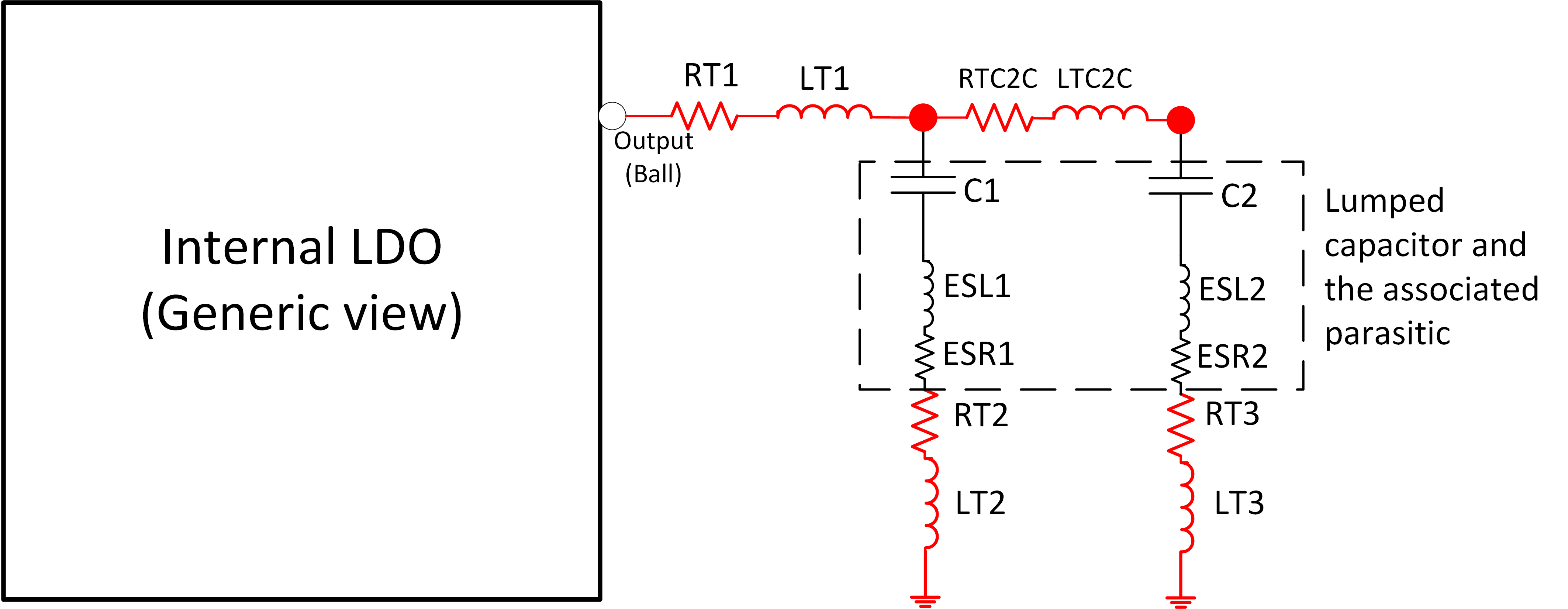
Figure 7-5 Parasitic offered by different portion of the output path (for two capacitors)
The parasitic offered by different portion of the output path is illustrated in Figure 7-5. As shown in figure, the output path can be divided into four portions:
Ball to first capacitor: “RT1” and “LT1” are the parasitic resistance and inductance offered by the ball to the first capacitor lead.
Along the first capacitor: “ESL1” and “ESR1” are the effective series inductance and resistance of the first decoupling capacitor. “RT2” and “LT2” are the ground trace resistance and inductance respectively of the first capacitor ground trace.
First capacitor lead to second capacitor lead: “RTC2C” and “LTC2C” are the resistance and inductance of the trace between two capacitors.
Along the second capacitor: “ESL2” and “ESR2” are the effective series inductance and resistance of the second decoupling capacitor. “RT3” and “LT3” are the ground trace resistance and inductance respectively of the second capacitor ground trace.