ZHCSD41A DECEMBER 2012 – November 2014 LM10011
PRODUCTION DATA.
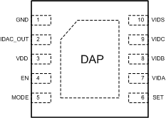
5 Pin Configuration and Functions
10-PIN
WSON PACKAGE
TOP VIEW

Pin Functions
| PIN | I/O | DESCRIPTION | |
|---|---|---|---|
| NAME | NUMBER | ||
| GND | 1 | – | Ground |
| IDAC_OUT | 2 | O | Output pin of the current DAC that connects to the feedback node of the regulator. |
| VDD | 3 | I | Positive supply input. Operating voltage is 2.97 V to 5.5 V. It is recommended to add a small 1-nF or greater bypass capacitor from this pin to GND. |
| EN | 4 | I | Precision enable input. The LM10011 will operate when the EN pin voltage exceeds 1.34 V. |
| MODE | 5 | – | MODE will set the VID operating mode. Connecting MODE to VDD will select a 4-bit parallel interface. Connecting MODE to GND will select a 4-pin, 6-bit interface. |
| SET | 6 | – | A resistor connected from SET to GND will set the start-up code (current) at the IDAC_OUT pin. There are 16 different start-up codes to select from. |
| VIDA | 7 | I | VID digital input. In 6-bit mode: Bit 0 when VIDS transitions low; Bit 3 when VIDS transitions high. In 4-bit mode: Bit 0. |
| VIDB | 8 | I | VID digital input. In 6-bit mode: Bit 1 when VIDS transitions low; Bit 4 when VIDS transitions high. In 4-bit mode: Bit 1. |
| VIDC | 9 | I | VID digital input. In 6-bit mode: Bit 2 when VIDS transitions low; Bit 5 when VIDS transitions high. In 4-bit mode: Bit 2. |
| VIDS | 10 | I | VID select line. In 6-bit mode: transition low selects lower 3 bits, transition high selects upper 3 bits and updates the IDAC_OUT current to reflect the present VID code. In 4-bit mode: Bit 3. |
| DAP | DAP | – | Die Attach Pad. Not electrically connected to device, connect to system ground plane for reduced thermal resistance. |