ZHCSCX2E January 2014 – October 2017 LM15851
PRODUCTION DATA.
- 1 特性
- 2 应用
- 3 说明
- 4 修订历史记录
- 5 Pin Configuration and Functions
- 6 Specifications
-
7 Detailed Description
- 7.1 Overview
- 7.2 Functional Block Diagram
- 7.3
Feature Description
- 7.3.1 Signal Acquisition
- 7.3.2 The Analog Inputs
- 7.3.3 Clocking
- 7.3.4 Over-Range Function
- 7.3.5 ADC Core Features
- 7.3.6
Digital Down Converter (DDC)
- 7.3.6.1 NCO/Mixer
- 7.3.6.2 NCO Settings
- 7.3.6.3 Decimation Filters
- 7.3.6.4 DDC Output Data
- 7.3.6.5 Decimation Settings
- 7.3.7
Data Outputs
- 7.3.7.1 The Digital Outputs
- 7.3.7.2
JESD204B Interface Features and Settings
- 7.3.7.2.1 Scrambler Enable
- 7.3.7.2.2 Frames Per Multi-Frame (K-1)
- 7.3.7.2.3 DDR
- 7.3.7.2.4 JESD Enable
- 7.3.7.2.5 JESD Test Modes
- 7.3.7.2.6 Configurable Pre-Emphasis
- 7.3.7.2.7 Serial Output-Data Formatting
- 7.3.7.2.8 JESD204B Synchronization Features
- 7.3.7.2.9 SYSREF
- 7.3.7.2.10 SYNC~
- 7.3.7.2.11 Code-Group Synchronization
- 7.3.7.2.12 Multiple ADC Synchronization
- 7.4 Device Functional Modes
- 7.5 Programming
- 7.6
Register Map
- 7.6.1 Memory Map
- 7.6.2
Register Descriptions
- 7.6.2.1
Standard SPI-3.0 (0x000 to 0x00F)
- Table 34. Standard SPI-3.0 Registers
- 7.6.2.1.1 Configuration A Register (address = 0x000) [reset = 0x3C]
- 7.6.2.1.2 Configuration B Register (address = 0x001) [reset = 0x00]
- 7.6.2.1.3 Device Configuration Register (address = 0x002) [reset = 0x00]
- 7.6.2.1.4 Chip Type Register (address = 0x003) [reset = 0x03]
- 7.6.2.1.5 Chip Version Register (address = 0x006) [reset = 0x13]
- 7.6.2.1.6 Vendor Identification Register (address = 0x00C to 0x00D) [reset = 0x0451]
- 7.6.2.2 User SPI Configuration (0x010 to 0x01F)
- 7.6.2.3
General Analog, Bias, Band Gap, and Track and Hold (0x020 to 0x02F)
- 7.6.2.3.1 Power-On Reset Register (address = 0x021) [reset = 0x00]
- 7.6.2.3.2 I/O Gain 0 Register (address = 0x022) [reset = 0x40]
- 7.6.2.3.3 IO_GAIN_1 Register (address = 0x023) [reset = 0x00]
- 7.6.2.3.4 I/O Offset 0 Register (address = 0x025) [reset = 0x40]
- 7.6.2.3.5 I/O Offset 1 Register (address = 0x026) [reset = 0x00]
- 7.6.2.4
Clock (0x030 to 0x03F)
- 7.6.2.4.1 Clock Generator Control 0 Register (address = 0x030) [reset = 0xC0]
- 7.6.2.4.2 Clock Generator Status Register (address = 0x031) [reset = 0x07]
- 7.6.2.4.3 Clock Generator Control 2 Register (address = 0x032) [reset = 0x80]
- 7.6.2.4.4 Analog Miscellaneous Register (address = 0x033) [reset = 0xC3]
- 7.6.2.4.5 Input Clamp Enable Register (address = 0x034) [reset = 0x2F]
- 7.6.2.5 Serializer (0x040 to 0x04F)
- 7.6.2.6
ADC Calibration (0x050 to 0x1FF)
- 7.6.2.6.1 Calibration Configuration 0 Register (address = 0x050) [reset = 0x06]
- 7.6.2.6.2 Calibration Configuration 1 Register (address = 0x051) [reset = 0xF4]
- 7.6.2.6.3 Calibration Background Control Register (address = 0x057) [reset = 0x10]
- 7.6.2.6.4 ADC Pattern and Over-Range Enable Register (address = 0x058) [reset = 0x00]
- 7.6.2.6.5 Calibration Vectors Register (address = 0x05A) [reset = 0x00]
- 7.6.2.6.6 Calibration Status Register (address = 0x05B) [reset = undefined]
- 7.6.2.6.7 Timing Calibration Register (address = 0x066) [reset = 0x02]
- 7.6.2.7
Digital Down Converter and JESD204B (0x200-0x27F)
- 7.6.2.7.1 Digital Down-Converter (DDC) Control Register (address = 0x200) [reset = 0x10]
- 7.6.2.7.2 JESD204B Control 1 Register (address = 0x201) [reset = 0x0F]
- 7.6.2.7.3 JESD204B Control 2 Register (address = 0x202) [reset = 0x00]
- 7.6.2.7.4 JESD204B Device ID (DID) Register (address = 0x203) [reset = 0x00]
- 7.6.2.7.5 JESD204B Control 3 Register (address = 0x204) [reset = 0x00]
- 7.6.2.7.6 JESD204B and System Status Register (address = 0x205) [reset = Undefined]
- 7.6.2.7.7 Overrange Threshold 0 Register (address = 0x206) [reset = 0xF2]
- 7.6.2.7.8 Overrange Threshold 1 Register (address = 0x207) [reset = 0xAB]
- 7.6.2.7.9 Overrange Period Register (address = 0x208) [reset = 0x00]
- 7.6.2.7.10 DDC Configuration Preset Mode Register (address = 0x20C) [reset = 0x00]
- 7.6.2.7.11 DDC Configuration Preset Select Register (address = 0x20D) [reset = 0x00]
- 7.6.2.7.12 Rational NCO Reference Divisor Register (address = 0x20E to 0x20F) [reset = 0x0000]
- 7.6.2.7.13 NCO Frequency (Preset x) Register (address = see ) [reset = see ]
- 7.6.2.7.14 NCO Phase (Preset x) Register (address = see ) [reset = see ]
- 7.6.2.7.15 DDC Delay (Preset x) Register (address = see ) [reset = see ]
- 7.6.2.1
Standard SPI-3.0 (0x000 to 0x00F)
- 8 Application and Implementation
- 9 Power Supply Recommendations
- 10Layout
- 11器件和文档支持
- 12机械、封装和可订购信息
11.1.3 器件命名规则
- 孔径(采样)延迟是在时钟输入的采样边沿测得的延迟量,经过此段延迟后将在器件内部对输入引脚的信号进行采样。
- 孔径抖动 (t(AJ))是采样与采样之间的孔径延迟变化。孔径抖动以输入噪声的形式出现。
- 时钟占空比是时钟波形为逻辑高电平的时间与一个时钟周期总时长的比率。
- 全功率带宽 (FPBW)是一个频率测量值,在此频率下,重构的输出基频会降至满量程输入的低频值以下 3dB。
- 交错毛刺是 ADC 多组交叉架构中的非理想条件产生的频域 (FFT) 效应。
各组间的偏移误差在 ƒS/4 和 ƒS/2 时会产生固定毛刺。增益和时序误差在 ƒS / 4 ± FIN 以及 ƒS / 2 ± FIN 时会产生输入信号相关毛刺。
- 互调失真 (IMD)是由于两个正弦频率同时被施加到 ADC 输入上所产生的额外频谱分量。IMD 定义为二阶和三阶互调米6体育平台手机版_好二三四功率与某原始频率下的功率之比。IMD 通常以 dBFS 为单位。
- 最低有效位 (LSB)是所有位中具有最小值或最低权重的位。此值根据Equation 18 进行计算。
- VFS(dif) 为 VI 的差分满量程幅值,如 FSR 输入所设(引脚 14)
- n 为 ADC 分辨率(以位为单位),LM15851器件对应的 n = 12
Equation 18. VFS(dif) / 2n
where
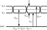
- 电流模式逻辑 (CML) 差分输出电压 (VOD)是正负输出电压间差值的绝对值。所有输出均相对于接地端测量。
 Figure 82. CML 输出信号电平
- CML 输出偏移电压 (VO(ofs))是 D+ 和 D– 引脚间输出电压的平均值。Equation 19 为 VOS 示例。
Equation 19. [(VD+) + ( VD–)] / 2
- 最高有效位 (MSB)是具有最大值或最高权重的位。MSB 的值为满量程的一半。
- 超量程恢复时间是转换器差分输入电压从 ±1.2V 变为 0V 后恢复并以额定精度进行转换所需的时间。
- 其它毛刺是所有高次谐波(四次及以上)、交错毛刺和所有其它固定毛刺或输入相关毛刺的总和。
- 数据延迟(延迟)是开始转换到串行器输出相关数据期间的输入时钟周期数。
- 无杂散动态范围 (SFDR)是输出端输入信号与杂散信号峰值的均方根 (RMS) 值间的差值(以 dB 为单位),其中杂散信号是出现在输出频谱但未出现在输入频谱的所有信号,直流信号除外。
- 总谐波失真 (THD)是输出端前九个谐波总值与输出端基频值之比的 RMS 值(以 dB 为单位)。总谐波失真 (THD) 根据Equation 20 计算。
- A(f1) 是基频(输出)的 RMS 功率
- A(f2) 到 A(f10) 是输出频谱中前九个谐波频率的 RMS 功率
Equation 20. 

where
- 二次谐波失真 (2nd Harm)是输出端检测到的输入频率 RMS 功率与输出端二次谐波功率之间的差值(以 dB 为单位)。
- 三次谐波失真 (3rd Harm)是输出端检测到的输入频率 RMS 功率与输出端三次谐波功率之间的差值(以 dB 为单位)。
- 误字率是出错率,定义为单位时间内可能出错的字数除以该时间内检查的字数。误字率 10–18 指大约每四年会有一个转换出现统计误差。