ZHCSIJ1E June 1999 – July 2018 LM2574 , LM2574HV
PRODUCTION DATA.
- 1 特性
- 2 应用
- 3 说明
- 4 修订历史记录
- 5 Pin Configuration and Functions
-
6 Specifications
- 6.1 Absolute Maximum Ratings
- 6.2 ESD Ratings
- 6.3 Recommended Operating Conditions
- 6.4 Thermal Information
- 6.5 Electrical Characteristics for All Output Voltage Versions
- 6.6 Electrical Characteristics – 3.3-V Version
- 6.7 Electrical Characteristics – 5-V Version
- 6.8 Electrical Characteristics – 12-V Version
- 6.9 Electrical Characteristics – 15-V Version
- 6.10 Electrical Characteristics – Adjustable Version
- 6.11 Typical Characteristics
- 7 Detailed Description
-
8 Application and Implementation
- 8.1 Application Information
- 8.2 Typical Applications
- 9 Power Supply Recommendations
- 10Layout
- 11器件和文档支持
- 12机械、封装和可订购信息
8.1.9.2 Negative Boost Regulator
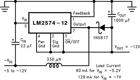
Another variation on the buck-boost topology is the negative boost configuration. The circuit in Figure 21 accepts an input voltage ranging from −5 V to −12 V and provides a regulated −12-V output. Input voltages greater than −12 V causes the output to rise greater than −12 V, but does not damage the regulator.

Because of the boosting function of this type of regulator, the switch current is relatively high, especially at low input voltages. Output load current limitations are a result of the maximum current rating of the switch. Also, boost regulators can not provide current-limiting load protection in the event of a shorted load, so some other means (such as a fuse) may be necessary.