SLVS075J April 1989 – January 2015 LM285-1.2 , LM385-1.2 , LM385B-1.2
PRODUCTION DATA.
- 1 Features
- 2 Applications
- 3 Description
- 4 Simplified Schematic
- 5 Revision History
- 6 Pin Configuration and Functions
- 7 Specifications
- 8 Detailed Description
- 9 Application and Implementation
- 10Power Supply Recommendations
- 11Layout
- 12Device and Documentation Support
- 13Mechanical, Packaging, and Orderable Information
9 Application and Implementation
NOTE
Information in the following applications sections is not part of the TI component specification, and TI does not warrant its accuracy or completeness. TI’s customers are responsible for determining suitability of components for their purposes. Customers should validate and test their design implementation to confirm system functionality.
9.1 Application Information
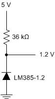
The The LM285-1.2, LM385-1.2, and LM385-1.2 devices create a voltage reference for to be used for a variety of applications including amplifiers, power supplies, and current-sensing circuits. The following application shows how to use these devices to establish a voltage reference.
9.2 Typical Application
 Figure 8. Generating Reference Voltage with a Resistive Current Source
9.2.1 Design Requirements
The key design requirement when using this device as a voltage reference is to supply the LM385 with a minimum Cathode Current (IZ), as indicated in Electrical Characteristics.
9.2.2 Detailed Design Procedure
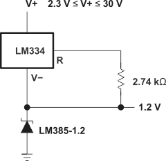
In order to generate a constant and stable reference voltage, a current greater than IZ(MIN) must be sourced into the cathode of this device. This can be accomplished using a current regulating device such as LM334 or a simple resistor. For a resistor, its value should be equal to or greater than (Vsupply - Vreference) ÷ IZ(MIN) .
9.2.3 Application Curves
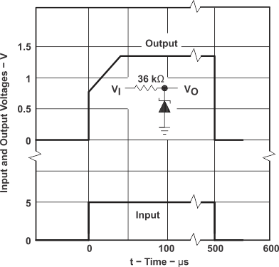
 Figure 9. Transient Response
9.3 System Examples
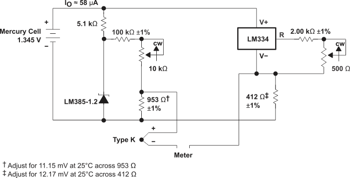
Thermocouple Cold-Junction Compensator
 Figure 10. Thermocouple Cold-Junction Compensator
Generating Reference Voltage with a Constant Current Source
 Figure 11. Generating Reference Voltage with a Constant Current Source Device