ZHCS531G September 2007 – January 2018 LM3103
PRODUCTION DATA.
7.2.9 Soft-Start
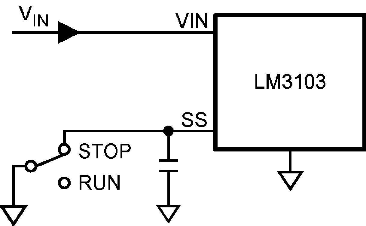
The soft-start feature allows the converter to gradually reach a steady state operating point, thereby reducing startup stresses and current surges. Upon turn-on, after VCC reaches the under-voltage threshold and a 180 µs fixed delay, a 70 µA internal current source charges an external capacitor CSS connecting to the SS pin. The ramping voltage at the SS pin (and the non-inverting input of the regulation comparator as well) ramps up the output voltage VOUT in a controlled manner. An internal switch grounds the SS pin if any of the following three cases happen: (i) VCC is below the under-voltage lockout threshold; (ii) a thermal shutdown occurs; or (iii) the EN pin is grounded. Alternatively, the output voltage can be shut off by connecting the SS pin to the ground using an external switch. Releasing the switch allows the voltage of the SS pin to ramp up and the output voltage to return to normal. The shutdown configuration is shown in Figure 21.
 Figure 21. Alternate Shutdown Implementation