-
LM5163-Q1 具有超低 IQ 的 100V 输入、0.5A 同步直流/直流降压转换器
- 1
- 1 特性
- 2 应用
- 3 说明
- 4 Pin Configuration and Functions
- 5 Specifications
-
6 Detailed Description
- 6.1 Overview
- 6.2 Functional Block Diagram
- 6.3
Feature Description
- 6.3.1 Control Architecture
- 6.3.2 Internal VCC Regulator and Bootstrap Capacitor
- 6.3.3 Regulation Comparator
- 6.3.4 Internal Soft Start
- 6.3.5 On-Time Generator
- 6.3.6 Current Limit
- 6.3.7 N-Channel Buck Switch and Driver
- 6.3.8 Synchronous Rectifier
- 6.3.9 Enable/Undervoltage Lockout (EN/UVLO)
- 6.3.10 Power Good (PGOOD)
- 6.3.11 Thermal Protection
- 6.4 Device Functional Modes
- 7 Application and Implementation
- 8 Device and Documentation Support
- 9 Revision History
- 10Mechanical, Packaging, and Orderable Information
- 重要声明
Data Sheet
LM5163-Q1 具有超低 IQ 的 100V 输入、0.5A 同步直流/直流降压转换器
本资源的原文使用英文撰写。 为方便起见,TI 提供了译文;由于翻译过程中可能使用了自动化工具,TI 不保证译文的准确性。 为确认准确性,请务必访问 ti.com 参考最新的英文版本(控制文档)。
1 特性
- 符合面向汽车应用的 AEC-Q100 标准
- 器件温度等级 1:–40°C 至 +125°C 的环境温度范围
- 专为可靠耐用的应用而设计
- 6V 至 100V 的宽输入电压范围
- 结温范围:–40°C 至 +150°C
- 固定 3ms 内部软启动计时器
- 峰值和谷值电流限制保护
- 输入 UVLO 和热关断保护
- 针对超低 EMI 要求进行了优化
- 适用于可扩展的汽车电源
- 最短导通时间和关闭时间低:50ns
- 高达 1MHz 的可调节开关频率
- 可实现高轻负载效率的二极管仿真
- 10.5µA 空载输入静态电流
- 3µA 关断静态电流
- 通过集成技术减小设计尺寸,降低成本
- COT 模式控制架构
- 集成式 0.725Ω NFET 降压开关
- 集成式 0.34Ω NFET 同步整流器省去了外部肖特基二极管
- 1.2V 内部电压基准
- 无环路补偿组件
- 内部 VCC 偏置稳压器和自举二极管
- 使用 WEBENCH® Power Designer 创建定制稳压器设计
3 说明
LM5163-Q1 同步降压转换器用于在宽输入电压范围内进行调节,从而最大限度地减少对外部浪涌抑制组件的需求。50ns 的最短可控导通时间有助于实现较大的降压比,支持从 48V 标称输入到低电压轨的直接降压转换,从而降低系统的复杂性并减少解决方案成本。LM5163-Q1 在输入电压突降至 6V 时,能够根据需要以接近 100% 的占空比工作,因此非常适合高性能 48V 电池汽车应用和 MHEV/EV 系统。
LM5163-Q1 具有集成式高侧和低侧功率 MOSFET,可提供高达 0.5A 的输出电流。恒定导通时间 (COT) 控制架构可提供几乎恒定的开关频率,具有出色的负载和线路瞬态响应。LM5163-Q1 的其他特性包括超低 IQ 和二极管仿真模式运行(可实现高轻负载效率)、创新的峰值和谷值过流保护、集成式 VCC 辅助电源和自举二极管、精密使能和输入 UVLO 以及具有自动恢复功能的热关断保护。开漏 PGOOD 指示器提供时序控制、故障报告和输出电压监视功能。
LM5163-Q1 符合汽车 AEC-Q100 1 级标准并采用 8 引脚 SO PowerPAD™ 封装。该器件的 1.27mm 引脚间距可以为高电压应用提供足够的间距。
(1) 有关更多信息,请参阅节 10。
(2) 封装尺寸(长 × 宽)为标称值,并包括引脚(如适用)。
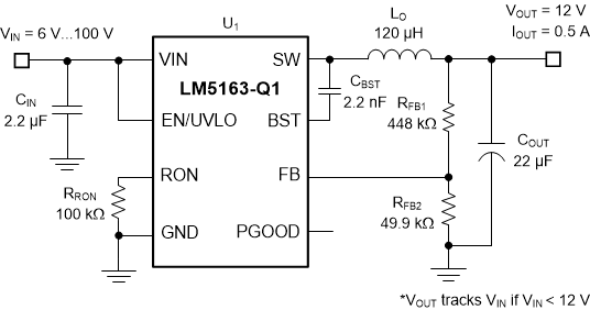
 典型应用
典型应用 典型应用效率,VOUT = 12V
4 Pin Configuration and Functions
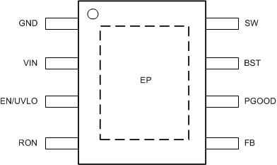
 Figure 4-1 DDA Package8-Pin SO PowerPAD™Top View
Table 4-1 Pin Functions
| PIN | TYPE(1) | DESCRIPTION | |
|---|---|---|---|
| NO. | NAME | ||
| 1 | GND | G | Ground connection for internal circuits |
| 2 | VIN | P/I | Regulator supply input pin to high-side power MOSFET and internal bias regulator. Connect directly to the input supply of the buck converter with short, low impedance paths. |
| 3 | EN/UVLO | I | Precision enable and undervoltage lockout (UVLO) programming pin. If the EN/UVLO voltage is below 1.1 V, the converter is in shutdown mode with all functions disabled. If the UVLO voltage is greater than 1.1 V and below 1.5 V, the converter is in standby mode with the internal VCC regulator operational and no switching. If the EN/UVLO voltage is above 1.5 V, the start-up sequence begins. |
| 4 | RON | I | On-time programming pin. A resistor between this pin and GND sets the buck switch on-time. |
| 5 | FB | I | Feedback input of voltage regulation comparator |
| 6 | PGOOD | O | Power good indicator. This pin is an open-drain output pin. Connect to a source voltage through an external pullup resistor between 10 kΩ to 100 kΩ. |
| 7 | BST | P/I | Bootstrap gate-drive supply. Required to connect a high-quality 2.2-nF 50-V X7R ceramic capacitor between BST and SW to bias the internal high-side gate driver. |
| 8 | SW | P | Switching node that is internally connected to the source of the high-side NMOS buck switch and the drain of the low-side NMOS synchronous rectifier. Connect to the switching node of the power inductor. |
| — | EP | — | Exposed pad of the package. No internal electrical connection. Solder the EP to the GND pin and connect to a large copper plane to reduce thermal resistance. |
(1) G = Ground, I = Input, O = Output, P = Power