ZHCSGX1F May 2004 – August 2017 LM60
PRODUCTION DATA.
7 Specifications
7.1 Absolute Maximum Ratings
over operating free-air temperature range (unless otherwise noted)(1)| MIN | MAX | UNIT | ||
|---|---|---|---|---|
| Supply voltage | −0.2 | 12 | V | |
| Output voltage | −0.6 | VS + 0.6 | V | |
| Output current | 10 | mA | ||
| Input current at any pin(2) | 5 | mA | ||
| Maximum junction temperature (TJMAX) | 125 | °C | ||
| Storage temperature (Tstg) | −65 | 150 | °C | |
(1) Stresses beyond those listed under Absolute Maximum Ratings may cause permanent damage to the device. These are stress ratings only, which do not imply functional operation of the device at these or any other conditions beyond those indicated under Recommended Operating Conditions. Exposure to absolute-maximum-rated conditions for extended periods may affect device reliability.
(2) When the input voltage (VI) at any pin exceeds power supplies (VI < GND or VI > +VS), the current at that pin should be limited to 5 mA.
7.2 ESD Ratings
| VALUE | UNIT | |||
|---|---|---|---|---|
| LM60 in DBZ Package | ||||
| V(ESD) | Electrostatic discharge(1) | Human-body model (HBM) | ±2500 | V |
| Machine model (MM) | ±250 | |||
| LM60 in LP Package | ||||
| V(ESD) | Electrostatic discharge(1) | Human-body model (HBM) | ±2500 | V |
| Machine model (MM) | ±200 | |||
(1) The human body model is a 100-pF capacitor discharged through a 1.5-kΩ resistor into each pin. The machine model is a 200-pF capacitor discharged directly into each pin.
7.3 Recommended Operating Conditions
over operating free-air temperature range (unless otherwise noted)(1)| MIN | MAX | UNIT | ||
|---|---|---|---|---|
| LM60B (TMIN ≤ TA ≤ TMAX) | –25(2) | 125 | °C | |
| LM60C (TMIN ≤ TA ≤ TMAX) | –40 | 125 | °C | |
| Supply voltage (+VS) | 2.7 | 10 | V | |
(1) Soldering process must comply with National Semiconductor's Reflow Temperature Profile specifications. Refer to www.national.com/packaging. Reflow temperature profiles are different for lead-free and non-lead-free packages.
(2) LM60B will operate down to –40°C without damage but the accuracy is only ensured from –25°C to 125°C.
7.4 Thermal Information
| THERMAL METRIC(1) | LM60 | UNIT | ||
|---|---|---|---|---|
| DBZ (SOT-23) | LP (TO-92) | |||
| 3 PINS | 3 PINS | |||
| RθJA(2) | Junction-to-ambient thermal resistance | 266 | 162 | °C/W |
| RθJC(top) | Junction-to-case (top) thermal resistance | 135 | 85 | °C/W |
| RθJB | Junction-to-board thermal resistance | 59 | — | °C/W |
| ψJT | Junction-to-top characterization parameter | 18 | 29 | °C/W |
| ψJB | Junction-to-board characterization parameter | 58 | 142 | °C/W |
(1) For more information about traditional and new thermal metrics, see the Semiconductor or IC Package Thermal Metrics application report.
(2) The junction to ambient thermal resistance (RθJA) is specified without a heat sink in still air.
7.5 Electrical Characteristics
Unless otherwise noted, these specifications apply for +VS = 3 VDC and ILOAD = 1 μA. All limits TA = TJ = 25°C unless otherwise noted.| PARAMETER | TEST CONDITIONS | MIN(2) | TYP(1) | MAX(2) | UNIT | ||
|---|---|---|---|---|---|---|---|
| Accuracy(3) | LM60B | –2 | 2 | °C | |||
| TA = TJ = TMIN to TMAX | –3 | 3 | |||||
| LM60C | –3 | 3 | °C | ||||
| TA = TJ = TMIN to TMAX | –4 | 4 | |||||
| Output voltage at 0°C | 424 | mV | |||||
| Nonlinearity(4) | LM60B | TA = TJ = TMIN to TMAX | –0.6 | ±0.6 | °C | ||
| LM60C | TA = TJ = TMIN to TMAX | –0.8 | ±0.8 | ||||
| Sensor gain (average slope) | 6.25 | mV/°C | |||||
| LM60B | TA = TJ = TMIN to TMAX | 6.06 | 6.44 | ||||
| LM60C | TA = TJ = TMIN to TMAX | 6 | 6.5 | ||||
| Output impedance | TA = TJ = TMIN to TMAX | 800 | Ω | ||||
| Line regulation(5) | 3 V ≤ +VS ≤ 10 V | TA = TJ = TMIN to TMAX | –0.3 | 0.3 | mV/V | ||
| 2.7 V ≤ +VS ≤ 3.3 V | TA = TJ = TMIN to TMAX | –2.3 | 2.3 | mV | |||
| Quiescent current | 2.7 V ≤ +VS ≤ 10 V | 82 | 110 | μA | |||
| TA = TJ = TMIN to TMAX | 125 | μA | |||||
| Change of quiescent current | 2.7 V ≤ +VS ≤ 10 V | ±5 | μA | ||||
| Temperature coefficient of quiescent current | 0.2 | μA/°C | |||||
| Long-term stability(6) | TJ = TMAX = 125°C for 1000 hours |
±0.2 | °C | ||||
(1) Typicals are at TJ = TA = 25°C and represent most likely parametric norm.
(2) Limits are specified to TI's AOQL (Average Outgoing Quality Level).
(3) Accuracy is defined as the error between the output voltage and 6.25 mV/°C times the case temperature of the device plus 424 mV, at specified conditions of voltage, current, and temperature (expressed in °C).
(4) Nonlinearity is defined as the deviation of the output-voltage-versus-temperature curve from the best-fit straight line, over the rated temperature range of the device.
(5) Regulation is measured at constant junction temperature, using pulse testing with a low duty cycle. Changes in output due to heating effects can be computed by multiplying the internal dissipation by the thermal resistance.
(6) For best long-term stability, any precision circuit will give best results if the unit is aged at a warm temperature, temperature cycled for at least 46 hours before long-term life test begins for both temperatures. This is especially true when a small (surface-mount) part is wave-soldered; allow time for stress relaxation to occur. The majority of the drift will occur in the first 1000 hours at elevated temperatures. The drift after 1000 hours will not continue at the first 1000 hour rate.
7.6 Typical Characteristics
To generate these curves, the device was mounted to a printed-circuit board as shown in Figure 20.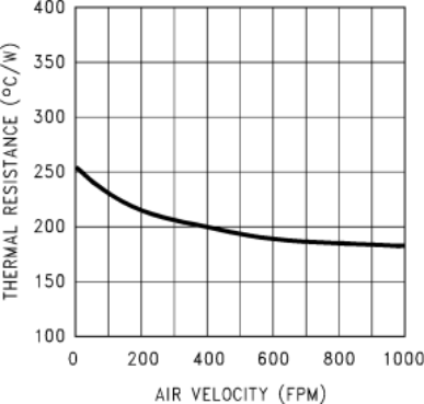 Figure 1. Thermal Resistance Junction to Air
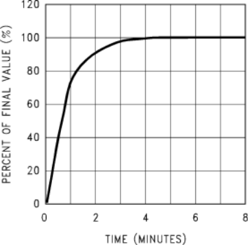 Figure 3. Thermal Response in Still Air With Heat Sink
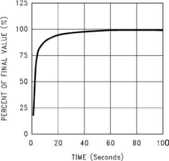 Figure 5. Thermal Response in Still Air Without a Heat Sink
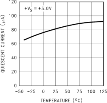 Figure 7. Quiescent Current vs Temperature
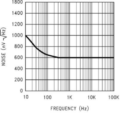 Figure 9. Noise Voltage
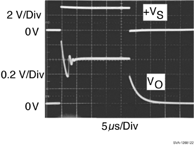 Figure 11. Start-Up Response
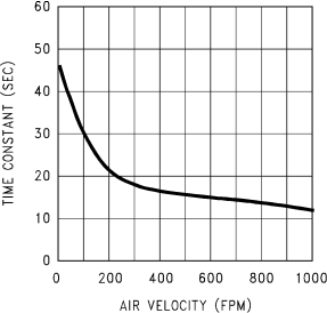 Figure 2. Thermal Time Constant
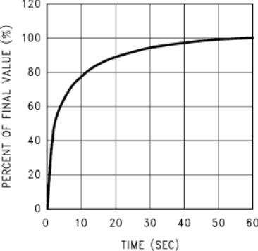 Figure 4. Thermal Response in Stirred Oil Bath With Heat Sink
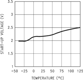 Figure 6. Start-Up Voltage vs Temperature
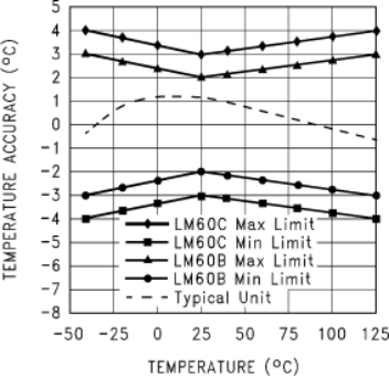 Figure 8. Accuracy vs Temperature
