ZHCSL46D March 2020 – June 2021 LM62440-Q1
PRODUCTION DATA
- 1 特性
- 2 应用
- 3 说明
- 4 Revision History
- 5 Description (continued)
- 6 Device Comparison Table
- 7 Pin Configuration and Functions
- 8 Specifications
-
9 Detailed Description
- 9.1 Overview
- 9.2 Functional Block Diagram
- 9.3
Feature Description
- 9.3.1 EN Uses for Enable and VIN UVLO
- 9.3.2 MODE/SYNC Pin Operation
- 9.3.3 PGOOD Output Operation
- 9.3.4 Internal LDO, VCC UVLO, and BIAS Input
- 9.3.5 Bootstrap Voltage and VCBOOT-UVLO (CBOOT Pin)
- 9.3.6 Adjustable SW Node Slew Rate
- 9.3.7 Spread Spectrum
- 9.3.8 Soft Start and Recovery From Dropout
- 9.3.9 Output Voltage Setting
- 9.3.10 Overcurrent and Short Circuit Protection
- 9.3.11 Thermal Shutdown
- 9.3.12 Input Supply Current
- 9.4 Device Functional Modes
-
10Application and Implementation
- 10.1 Application Information
- 10.2
Typical Application
- 10.2.1 Design Requirements
- 10.2.2
Detailed Design Procedure
- 10.2.2.1 Choosing the Switching Frequency
- 10.2.2.2 Setting the Output Voltage
- 10.2.2.3 Inductor Selection
- 10.2.2.4 Output Capacitor Selection
- 10.2.2.5 Input Capacitor Selection
- 10.2.2.6 BOOT Capacitor
- 10.2.2.7 BOOT Resistor
- 10.2.2.8 VCC
- 10.2.2.9 BIAS
- 10.2.2.10 CFF and RFF Selection
- 10.2.2.11 External UVLO
- 10.2.3 Application Curves
- 11Power Supply Recommendations
- 12Layout
- 13Device and Documentation Support
- 14Mechanical, Packaging, and Orderable Information
3 说明
LM62440-Q1 是一款汽车专用的高性能直流/直流同步降压转换器。该器件具有集成式高侧和低侧 MOSFET,能够在 3.0V 至 36V 的宽输入电压范围内提供高达 4A 的输出电流;可耐受 42V 电压,支持 400ms 时长的负载突降。LM62440-Q1 可对压降进行软恢复,因此无需对输出进行过冲。
LM62440-Q1 专门设计用于降低 EMI。该器件具有假随机展频、可调节 SW 节点上升时间和低 EMI,并采用具有低开关节点振铃和易于使用、优化型引脚排列的 VQFN-HR 封装。开关频率可在 200kHz 至 2.2MHz 范围内同步,从而避开噪声敏感频段。另外,可以选择频率,从而在低工作频率下提高效率,或在高工作频率下缩小解决方案尺寸。
自动模式可在轻负载运行时进行频率折返,实现仅 7µA(典型值)的空载电流消耗和高轻负载效率。PWM 和 PFM 模式之间无缝转换,以及极低的 MOSFET 导通电阻和外部偏置输入,均确保在整个负载范围内实现卓越的效率。
器件信息
| 器件型号 | 封装(1) | 封装尺寸(标称值) |
|---|---|---|
| LM62440-Q1 | VQFN-HR (14) | 4.00mm × 3.50mm |
(1) 如需了解所有可用封装,请参阅数据表末尾的可订购米6体育平台手机版_好二三四附录。
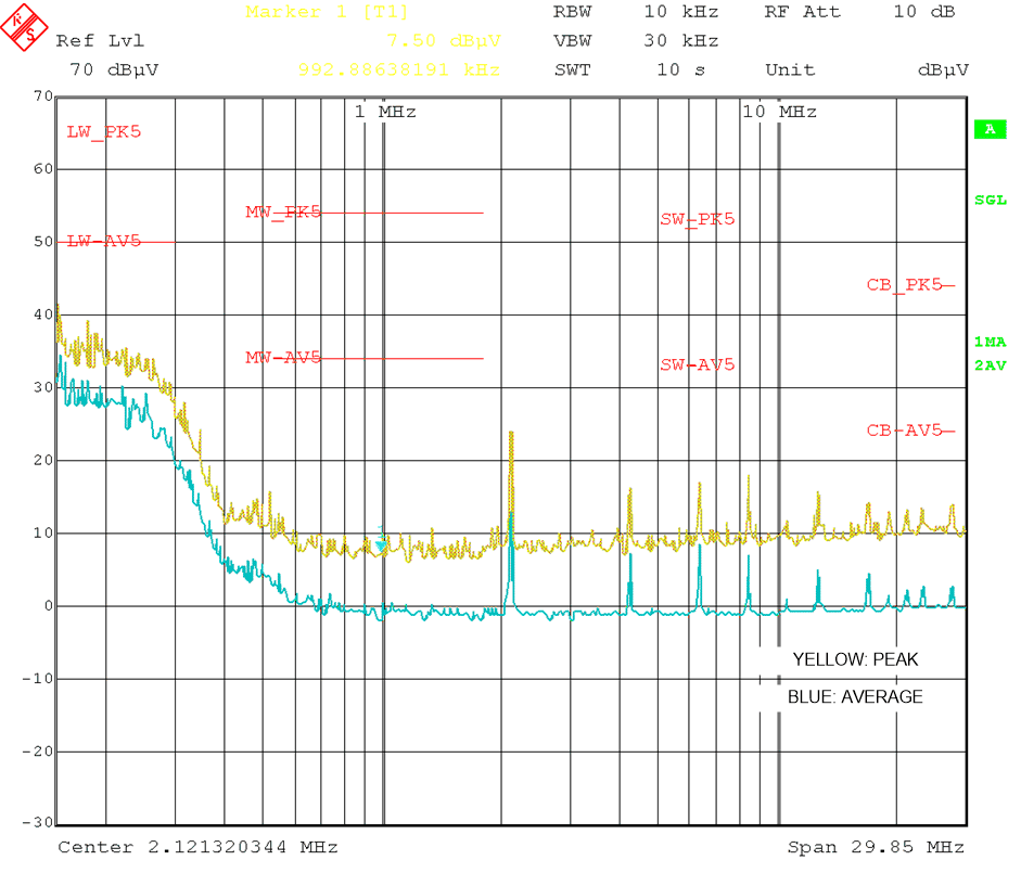
 传导 EMI:VOUT=5V,fSW=2100kHz
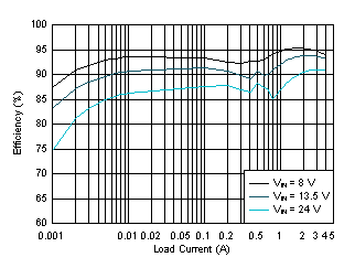
 效率:VOUT = 5V、FSW = 2200kHz