ZHCSQT8 October 2023 LM74930-Q1
PRODUCTION DATA
- 1
- 1 特性
- 2 应用
- 3 说明
- 4 Revision History
- 5 Pin Configuration and Functions
- 6 Specifications
-
7 Detailed Description
- 7.1 Overview
- 7.2 Functional Block Diagram
- 7.3
Feature Description
- 7.3.1 Charge Pump
- 7.3.2 Dual Gate Control (DGATE, HGATE)
- 7.3.3 Overcurrent Protection (CS+, CS-, ILIM, IMON, TMR)
- 7.3.4 Overcurrent Protection with Circuit Breaker (ILIM, TMR)
- 7.3.5 Overcurrent Protection With Latch-Off
- 7.3.6 Short-Circuit Protection (ISCP)
- 7.3.7 Analog Current Monitor Output (IMON)
- 7.3.8 Overvoltage and Undervoltage Protection (OV, UVLO, OVCLAMP)
- 7.3.9 Disabling Reverse Current Blocking Functionality (MODE)
- 7.3.10 Device Functional Modes
-
8 Applications and Implementation
- 8.1 Application Information
- 8.2
Typical Application: 200-V Unsuppressed Load Dump Protection Application
- 8.2.1 Design Requirements for 200-V Unsuppressed Load Dump Protection
- 8.2.2
Detailed Design Procedure
- 8.2.2.1 VS Capacitance, Resistor R1 and Zener Clamp (DZ)
- 8.2.2.2 Charge Pump Capacitance VCAP
- 8.2.2.3 Input and Output Capacitance
- 8.2.2.4 Overvoltage and Undervoltage Protection Component Selection
- 8.2.2.5 Selection of Scaling Resistor (RSET) and Short-Circuit Protection Setting Resistor (RSCP)
- 8.2.2.6 Overcurrent Limit (ILIM), Circuit Breaker Timer (TMR), and Current Monitoring Output (IMON) Selection
- 8.2.2.7 Selection of Current Sense Resistor, RSNS
- 8.2.2.8 Hold-Up Capacitance
- 8.2.2.9 MOSFET Q1 Selection
- 8.2.2.10 MOSFET Q2 Selection
- 8.2.2.11 Input TVS Selection
- 8.2.3 Application Curves
- 8.3 Best Design Practices
- 8.4 Power Supply Recommendations
- 8.5 Layout
- 9 Device and Documentation Support
- 10Mechanical, Packaging, and Orderable Information
3 说明
LM74930-Q1 理想二极管控制器可驱动和控制外部背对背 N 沟道 MOSFET,从而模拟理想二极管整流器和电源路径开/关控制,并提供过流和过压保护功能。4 V 至 65V 的宽输入电源电压可保护和控制 12V 和 24V 汽车类电池供电的 ECU。该器件可承受并保护负载免受低至 –65V 的负电源电压的影响。集成的高侧栅极控制 (HGATE) 可驱动电源路径中的第一个 MOSFET。该器件使用 HGATE 控制功能在发生过流、过压和欠压事件时允许负载断开(开/关控制),同时理想二极管控制器 (DGATE) 可驱动第二个 MOSFET 来代替肖特基二极管,从而通过阻止反向电流从输出端流到输入端来实现输入反极性保护和输出电压保持。该器件具有集成的电流检测放大器,通过断路器功能提供可调节的过流和短路保护。该器件具有可调节过压和欠压保护功能,可防止电源瞬变。LM74930-Q1 有一个 MODE 引脚可用于选择性地启用或禁用反向电流阻断功能。
(1) 如需了解所有可用封装,请参阅数据表末尾的可订购米6体育平台手机版_好二三四附录。
(2) 封装尺寸(长 × 宽)为标称值,并包括引脚(如适用)。
 具有 200V 负载突降保护功能的理想二极管
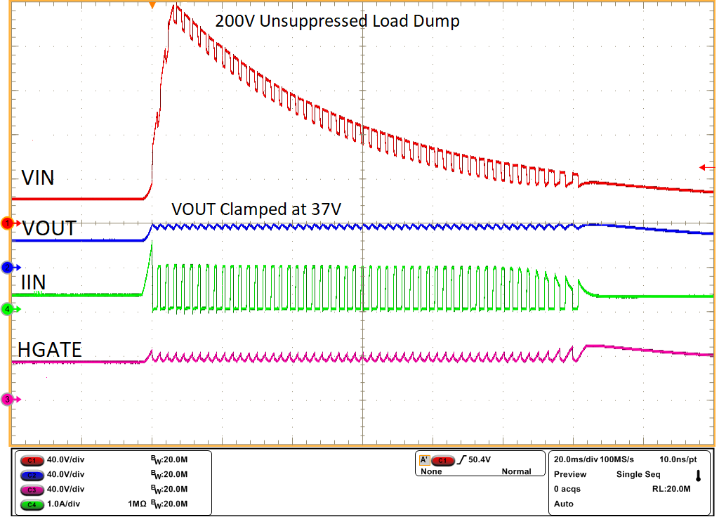
 未抑制的负载突降 200V - 输出钳位