ZHCSH05A October 2017 – October 2019 LM76002 , LM76003
PRODUCTION DATA.
- 1 特性
- 2 应用
- 3 说明
- 4 修订历史记录
- 5 Pin Configuration and Functions
- 6 Specifications
-
7 Detailed Description
- 7.1 Overview
- 7.2 Functional Block Diagram
- 7.3
Feature Description
- 7.3.1 Fixed-Frequency, Peak-Current-Mode Control
- 7.3.2 Light Load Operation Modes — PFM and FPWM
- 7.3.3 Adjustable Output Voltage
- 7.3.4 Enable (EN Pin) and UVLO
- 7.3.5 Internal LDO, VCC UVLO, and Bias Input
- 7.3.6 Soft Start and Voltage Tracking (SS/TRK)
- 7.3.7 Adjustable Switching Frequency (RT) and Frequency Synchronization
- 7.3.8 Minimum On-Time, Minimum Off-Time, and Frequency Foldback at Dropout Conditions
- 7.3.9 Internal Compensation and CFF
- 7.3.10 Bootstrap Voltage and VBOOT UVLO (BOOT Pin)
- 7.3.11 Power Good and Overvoltage Protection (PGOOD)
- 7.3.12 Overcurrent and Short-Circuit Protection
- 7.3.13 Thermal Shutdown
- 7.4 Device Functional Modes
-
8 Application and Implementation
- 8.1 Application Information
- 8.2
Typical Applications
- 8.2.1 Design Requirements
- 8.2.2
Detailed Design Procedure
- 8.2.2.1 Custom Design With WEBENCH® Tools
- 8.2.2.2 Output Voltage Setpoint
- 8.2.2.3 Switching Frequency
- 8.2.2.4 Input Capacitors
- 8.2.2.5 Inductor Selection
- 8.2.2.6 Output Capacitor Selection
- 8.2.2.7 Feed-Forward Capacitor
- 8.2.2.8 Bootstrap Capacitors
- 8.2.2.9 VCC Capacitors
- 8.2.2.10 BIAS Capacitors
- 8.2.2.11 Soft-Start Capacitors
- 8.2.2.12 Undervoltage Lockout Setpoint
- 8.2.2.13 PGOOD
- 8.2.2.14 Synchronization
- 8.2.3 Application Curves
- 9 Power Supply Recommendations
- 10Layout
- 11器件和文档支持
- 12机械、封装和可订购信息
3 说明
LM76002/LM76003 稳压器是一款易于使用的同步降压直流/直流转换器,能驱动高达 2.5A (LM76002) 或 3.5A (LM76003) 的负载电流,输入电压最高可达 60V。LM76002/LM76003 解决方案尺寸极小,但能提供优异的效率和输出精度。采用峰值电流模式控制。可调 特性 (例如可调开关频率、同步、FPWM 选项、电源正常状态标志、精密使能端、可调式软启动和跟踪)可为各种应用提供灵活且简单易用的 解决方案。轻负载时的自动频率折返和可选的外部偏置电源可以提高效率。该器件需要极少的外部组件,其引脚专为简化 PCB 布局而设计,可提供优异的 EMI (CISPR22) 和热性能。保护 功能 包括输入欠压锁定、热关断、逐周期电流限制和短路保护。LM76002/LM76003 器件采用 WQFN 30 引脚无引线式封装,且具有可湿性侧面。
器件信息(1)
| 器件型号 | 封装 | 封装尺寸(标称值) |
|---|---|---|
| LM76002 | WQFN (30) | 6.00mm × 4.00mm |
| LM76003 |
- 如需了解所有可用封装,请参阅数据表末尾的可订购米6体育平台手机版_好二三四附录。
空白
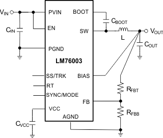
简化原理图

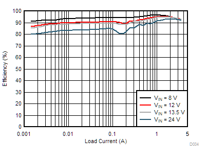
效率与输出电流
(VOUT = 5V,fSW = 400kHz,自动模式)
