SNIS146B March 2007 – October 2017 LM95214
PRODUCTION DATA.
- 1 Features
- 2 Applications
- 3 Description
- 4 Revision History
- 5 Pin Configuration and Functions
-
6 Specifications
- 6.1 Absolute Maximum Ratings
- 6.2 ESD Ratings
- 6.3 Recommended Operating Conditions
- 6.4 Thermal Information
- 6.5 Electrical Characteristics: Temperature-to-Digital Converter
- 6.6 Logic Electrical Characteristics: Digital DC Characteristics
- 6.7 Switching Characteristics: SMBus Digital
- 6.8 Typical Characteristics
-
7 Detailed Description
- 7.1 Overview
- 7.2 Functional Block Diagram
- 7.3 Feature Description
- 7.4 Device Functional Modes
- 7.5 Register Maps
- 8 Application and Implementation
- 9 Power Supply Recommendations
- 10Layout
- 11Device and Documentation Support
- 12Mechanical, Packaging, and Orderable Information
8 Application and Implementation
NOTE
Information in the following applications sections is not part of the TI component specification, and TI does not warrant its accuracy or completeness. TI’s customers are responsible for determining suitability of components for their purposes. Customers should validate and test their design implementation to confirm system functionality.
8.1 Application Information
The LM95214 can be applied easily in the same way as other integrated-circuit temperature sensors, and its remote diode sensing capability allows it to be used in new ways as well. It can be soldered to a printed-circuit board, and because the path of best thermal conductivity is between the die and the pins, its temperature will effectively be that of the printed-circuit board lands and traces soldered to the LM95214's pins. This presumes that the ambient air temperature is almost the same as the surface temperature of the printed-circuit board; if the air temperature is much higher or lower than the surface temperature, the actual temperature of the LM95214 die will be at an intermediate temperature between the surface and air temperatures. Again, the primary thermal conduction path is through the leads, so the circuit board temperature will contribute to the die temperature much more strongly than will the air temperature.
8.2 Typical Application
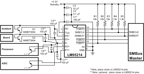
To measure temperature external to the LM95214's die, incorporates remote diode sensing technology. This diode can be located on the die of a target IC, allowing measurement of the IC's temperature, independent of the LM95214's temperature. A discrete diode can also be used to sense the temperature of external objects or ambient air. Remember that a discrete diode's temperature will be affected, and often dominated, by the temperature of its leads. Most silicon diodes do not lend themselves well to this application. TI recommends that an MMBT3904 transistor base emitter junction be used with the collector tied to the base.
The LM95214 can measure a diode-connected transistor such as the MMBT3904 or the thermal diode found in an AMD processor. The LM95214 has been optimized to measure the MMBT3904 remote thermal diode the offset register can be used to calibrate for other thermal diodes easily. The LM95214 does not include TruTherm™ technology that allows sensing of sub-micron geometry process thermal diodes. For this application the LM95234 would be better suited.
The LM95234 has been specifically optimized to measure the remote thermal diode integrated in a typical Intel processor on 65 nm or 90 nm process or an MMBT3904 transistor. Using the Remote Diode Model Select register found in the LM95234 any of the four remote inputs can be optimized for a typical Intel processor on 65 nm or 90 nm process or an MMBT3904.
 Figure 25. Typical Application
8.2.1 Design Requirements
The LM95214 operates only as a slave device and communicates with the host through the SMBus serial interface essentially compatible with I2C. SMBCLK is the clock input pin, SMBDATA is a bidirectional data pin, and TCRIT1, TCRIT2, TCRIT3 are the output pins. The LM95214 requires a pullup resistor on the SMBCLK, SMBDATA, and TCRIT1, TCRIT2, TCRIT3 pins due to an open-drain output. It is very important to consider the pullup resistor for the I2C systems. The recommended value for the pullup resistors is in Figure 25. Use a ceramic capacitor type with a temperature rating from –40°C to +125°C, placed as close as possible to the VDD pin of the LM95214. The decoupling capacitor reduces any noise induced by the system. A0 (pin 6) can be connected to either Low, Mid-Supply or High voltages for address selection for configuring three possible unique slave ID addresses; SMBus Interface explains the addressing scheme.
8.3 Diode Non-Ideality
8.3.1 Diode Non-Ideality Factor Effect on Accuracy
When a transistor is connected as a diode, the following relationship holds for variables VBE, T and IF:

where
-

- q = 1.6 × 10⁻¹⁹ Coulombs (the electron charge)
- T = Absolute Temperature in Kelvin
- k = 1.38 × 10⁻²³ joules/K (Boltzmann's constant)
- η is the non-ideality factor of the process the diode is manufactured on
- IS = Saturation Current and is process dependent
- If = Forward Current through the base-emitter junction
- VBE = Base-Emitter Voltage drop
In the active region, the –1 term is negligible and may be eliminated, yielding Equation 2

In Equation 2, η and IS are dependant upon the process that was used in the fabrication of the particular diode. By forcing two currents with a very controlled ratio(IF2 / IF1) and measuring the resulting voltage difference, it is possible to eliminate the IS term. Solving for the forward voltage difference yields the relationship:

Solving Equation 3 for temperature yields:

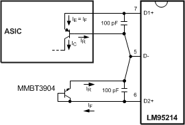
Equation 4 holds true when a diode connected transistor such as the MMBT3904 is used. When this diode equation is applied to an integrated diode such as a processor transistor with its collector tied to GND as shown in Figure 26 it will yield a wide non-ideality spread. This wide non-ideality spread is not due to true process variation but due to the fact that Equation 4 is an approximation.
Texas Instruments invented TruTherm beta cancellation technology that uses the transistor equation, Equation 5, which is a more accurate representation of the topology of the thermal diode found in some sub-micron FPGAs or processors.

 Figure 26. Thermal Diode Current Paths
TruTherm technology can be found in the LM95234 four channel remote diode sensor that is pin and register compatible with the LM95214. The LM95214 does not support this technology.
8.3.2 Calculating Total System Accuracy
The voltage seen by the LM95214 also includes the IFRS voltage drop of the series resistance. The non-ideality factor, η, is the only other parameter not accounted for and depends on the diode that is used for measurement. Because ΔVBE is proportional to both η and T, the variations in η cannot be distinguished from variations in temperature. Because the non-ideality factor is not controlled by the temperature sensor, it will directly add to the inaccuracy of the sensor. For the for Intel processor on 65 nm process, Intel specifies a +4.06%/−0.897% variation in η from part to part when the processor diode is measured by a circuit that assumes diode equation, Equation 4, as true. As an example, assume a temperature sensor has an accuracy specification of ±1.0°C at a temperature of 80°C (353 Kelvin) and the processor diode has a non-ideality variation of +1.19%/−0.27%. The resulting system accuracy of the processor temperature being sensed will be:
and
The next error term to be discussed is that due to the series resistance of the thermal diode and printed-circuit board traces. The thermal diode series resistance is specified on most processor data sheets. For the MMBT3904 transistor, this is specified at 0 Ω typical. The LM95214 accommodates the typical series resistance of a circuit with the offset register compensation. The error that is not accounted for is the spread of the thermal diodes series resistance. If a circuit has a series resistance spread that is 2.79 Ω to 6.24 Ω or 4.515 Ω ±1.73 Ω, the 4.515 Ω can be cancelled out with the offset register setting. The ±1.73 Ω spread cannot be cancelled out. The equation to calculate the temperature error due to series resistance (TER) for the LM95214 is simply:

Solving Equation 6 for RPCB equal to ±1.73 Ω results in the additional error due to the spread in the series resistance of ±1.07°C. The bulk of the error caused by the 4.515 Ω will cause a positive offset in the temperature reading of 2.79°C, which can be cancelled out by setting the offset register to –2.75°C. The spread in error cannot be canceled out, as it would require measuring each individual thermal diode device. This is quite difficult and impractical in a large volume production environment.
Equation 6 can also be used to calculate the additional error caused by series resistance on the printed circuit board. Because the variation of the PCB series resistance is minimal, the bulk of the error term is always positive and can simply be cancelled out by subtracting it from the output readings of the LM95214.
| PROCESSOR FAMILY | DIODE EQUATION ηD, non-ideality | SERIES R,Ω | ||
|---|---|---|---|---|
| MIN | TYP | MAX | ||
| Pentium III CPUID 67h | 1 | 1.0065 | 1.0125 | |
| Pentium III CPUID 68h/PGA370Socket/ Celeron |
1.0057 | 1.008 | 1.0125 | |
| Pentium 4, 423 pin | 0.9933 | 1.0045 | 1.0368 | |
| Pentium 4, 478 pin | 0.9933 | 1.0045 | 1.0368 | |
| Pentium 4 on 0.13 micron process, 2 - 3.06 GHz | 1.0011 | 1.0021 | 1.0030 | 3.64 |
| Pentium 4 on 90 nm process | 1.0083 | 1.011 | 1.023 | 3.33 |
| Intel Processor on 65 nm process | 1.000 | 1.009 | 1.050 | 4.52 |
| Pentium M (Centrino) | 1.00151 | 1.00220 | 1.00289 | 3.06 |
| MMBT3904 | 1.003 | |||
| AMD Athlon MP model 6 | 1.002 | 1.008 | 1.016 | |
| AMD Athlon 64 | 1.008 | 1.008 | 1.096 | |
| AMD Opteron | 1.008 | 1.008 | 1.096 | |
| AMD Sempron | 1.00261 | 0.93 | ||
8.3.3 Compensating for Different Non-Ideality
To compensate for the errors introduced by non-ideality, the temperature sensor is calibrated for a particular processor. Texas Instruments temperature sensors are always calibrated to the typical non-ideality and series resistance of a given transistor type. The LM95214 is calibrated for the non-ideality factor and series resistance values of the MMBT3904 transistor without the requirement for additional trims. When a temperature sensor calibrated for a particular thermal diode type is used with a different thermal diode type, additional errors are introduced.
Temperature errors associated with non-ideality of different processor types may be reduced in a specific temperature range of concern through use of software calibration. Typical Non-ideality specification differences cause a gain variation of the transfer function, therefore the center of the temperature range of interest must be the target temperature for calibration purposes. The Equation 7 can be used to calculate the temperature correction factor (TCF) required to compensate for a target non-ideality differing from that supported by the LM95214.

where
- ηS = LM95214 non-ideality for accuracy specification
- ηPROCESSOR = Processor thermal diode typical non-ideality
- TCR = center of the temperature range of interest in °C
The correction factor must be directly added to the temperature reading produced by the LM95214. For example when using the LM95214, with the 3904 mode selected, to measure a AMD Athlon processor, with a typical non-ideality of 1.008, for a temperature range of 60°C to 100°C the correction factor would calculate to:

Therefore, 1.75°C must be subtracted from the temperature readings of the LM95214 to compensate for the differing typical non-ideality target.