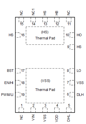
| BST |
17 |
O |
Bootstrap diode anode connection point. |
| DHL |
5 |
I |
Sets the dead time for a high-to-low transition in PWM mode by connecting a resistor to VSS. If using IIM this pin can be left floating, tied to GND, tied to VDD. |
| DLH |
6 |
I |
Sets the dead time for a low-to-high transition in PWM mode by connecting a resistor to VSS. Tie to VDD to select IIM. |
| EN/HI |
18 |
I |
Enable input or high-side driver control. In PWM mode this is the EN pin. In IIM mode this is the HI pin. |
| PWM/LI |
19 |
I |
PWM input or low-side driver control. In PWM mode this is the PWM pin. In IIM mode this is the LI pin. |
| HB |
12 |
I |
High-side driver supply. Bootstrap diode cathode connection point. |
| HO |
10 |
O |
High-side driver output. |
| HS |
9,13,16 |
I |
Switch node and high-side driver ground. These pins are internally connected. |
| LO |
8 |
O |
Low-side driver output. |
| NC |
1,11,15 |
— |
Not internally connected. |
| NC1 |
14 |
I |
For proper operation, this pin should be either unconnected or tied to HS. |
| Thermal Pad (HS) |
21 |
I |
Connected to HS. |
| Thermal Pad (VSS) |
20 |
I |
Connected to VSS. |
| VDD |
4 |
O |
Low-side driver supply and LDO output. 5 V |
| VIN |
2 |
I |
6 V to 18 V input to LDO. If LDO is not required, connect to VDD. |
| VSS |
3,7 |
— |
Low-side ground return: all low-side signals are referenced to this ground. |

