ZHCSJF9A March 2019 – June 2019 LMG3410R150 , LMG3411R150
ADVANCE INFORMATION for pre-production products; subject to change without notice.
- 1 特性
- 2 应用
- 3 说明
- 4 修订历史记录
- 5 Pin Configuration and Functions
- 6 Specifications
- 7 Parameter Measurement Information
- 8 Detailed Description
- 9 Application and Implementation
- 10Power Supply Recommendations
- 11Layout
- 12器件和文档支持
- 13机械、封装和可订购信息
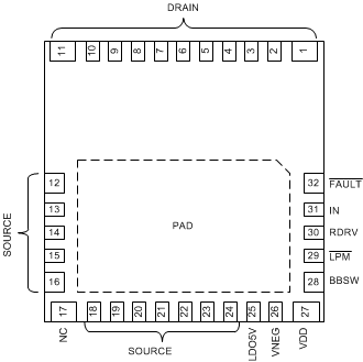
5 Pin Configuration and Functions
RWH (QFN) PACKAGE
32 PINS
(Top View)

Pin Functions
| PIN | I/O(1) | DESCRIPTION | |
|---|---|---|---|
| NAME | NO. | ||
| BBSW | 28 | P | Internal buck-boost converter switch pin. Connect an inductor from this point to source |
| DRAIN | 1-11 | P | Power transistor drain |
| FAULT | 32 | O | Fault output, push-pull, active low |
| IN | 31 | I | CMOS-compatible non-inverting gate drive input |
| LDO5V | 25 | P | 5-V LDO output for external digital isolator. |
| LPM | 29 | I | Enables low-power-mode by connecting the pin to source |
| SOURCE | 12-16, 18-24 | P | Power transistor source, die-attach pad, thermal sink, signal ground reference |
| RDRV | 30 | I | Drive strength selection pin. Connect a resistor from this pin to ground to set the turn-on drive strength to control slew rate, |
| VDD | 27 | P | 12-V power input, relative to source. Supplies 5-V rail and gate drive supply. |
| VNEG | 26 | P | Negative supply output, bypass to source with 1-µF capacitor |
| NC | 17 | — | Not connected, connect to source or leave floating. |
| PAD | — | P | Thermal Pad, tie to source with multiple vias. |
(1) I = Input, O = Output, P = Power