ZHCSM56D September   2020  – March 2022 LMG3422R030 , LMG3425R030

PRODUCTION DATA  

  1. 特性
  2. 应用
  3. 说明
  4. Revision History
  5. Device Comparison
  6. Pin Configuration and Functions
  7. Specifications
    1. 7.1 Absolute Maximum Ratings
    2. 7.2 ESD Ratings
    3. 7.3 Recommended Operating Conditions
    4. 7.4 Thermal Information
    5. 7.5 Electrical Characteristics
    6. 7.6 Switching Characteristics
    7. 7.7 Typical Characteristics
  8. Parameter Measurement Information
    1. 8.1 Switching Parameters
      1. 8.1.1 Turn-On Times
      2. 8.1.2 Turn-Off Times
      3. 8.1.3 Drain-Source Turn-On Slew Rate
      4. 8.1.4 Turn-On and Turn-Off Switching Energy
  9. Detailed Description
    1. 9.1 Overview
    2. 9.2 Functional Block Diagram
    3. 9.3 Feature Description
      1. 9.3.1  GaN FET Operation Definitions
      2. 9.3.2  Direct-Drive GaN Architecture
      3. 9.3.3  Drain-Source Voltage Capability
      4. 9.3.4  Internal Buck-Boost DC-DC Converter
      5. 9.3.5  VDD Bias Supply
      6. 9.3.6  Auxiliary LDO
      7. 9.3.7  Fault Detection
        1. 9.3.7.1 Overcurrent Protection and Short-Circuit Protection
        2. 9.3.7.2 Overtemperature Shutdown
        3. 9.3.7.3 UVLO Protection
        4. 9.3.7.4 Fault Reporting
      8. 9.3.8  Drive Strength Adjustment
      9. 9.3.9  Temperature-Sensing Output
      10. 9.3.10 Ideal-Diode Mode Operation
    4. 9.4 Device Functional Modes
  10. 10Application and Implementation
    1. 10.1 Application Information
    2. 10.2 Typical Application
      1. 10.2.1 Design Requirements
      2. 10.2.2 Detailed Design Procedure
        1. 10.2.2.1 Slew Rate Selection
          1. 10.2.2.1.1 Start-Up and Slew Rate With Bootstrap High-Side Supply
        2. 10.2.2.2 Signal Level-Shifting
        3. 10.2.2.3 Buck-Boost Converter Design
      3. 10.2.3 Application Curves
    3. 10.3 Do's and Don'ts
  11. 11Power Supply Recommendations
    1. 11.1 Using an Isolated Power Supply
    2. 11.2 Using a Bootstrap Diode
      1. 11.2.1 Diode Selection
      2. 11.2.2 Managing the Bootstrap Voltage
  12. 12Layout
    1. 12.1 Layout Guidelines
      1. 12.1.1 Solder-Joint Reliability
      2. 12.1.2 Power-Loop Inductance
      3. 12.1.3 Signal-Ground Connection
      4. 12.1.4 Bypass Capacitors
      5. 12.1.5 Switch-Node Capacitance
      6. 12.1.6 Signal Integrity
      7. 12.1.7 High-Voltage Spacing
      8. 12.1.8 Thermal Recommendations
    2. 12.2 Layout Examples
  13. 13Device and Documentation Support
    1. 13.1 Documentation Support
      1. 13.1.1 Related Documentation
    2. 13.2 接收文档更新通知
    3. 13.3 支持资源
    4. 13.4 Trademarks
    5. 13.5 Electrostatic Discharge Caution
    6. 13.6 Export Control Notice
    7. 13.7 术语表
  14. 14Mechanical, Packaging, and Orderable Information

封装选项

请参考 PDF 数据表获取器件具体的封装图。

机械数据 (封装 | 引脚)
  • RQZ|54
散热焊盘机械数据 (封装 | 引脚)
订购信息

说明

LMG342xR030 GaN FET 具有集成式驱动器和保护功能,可让设计人员在电力电子系统中实现更高水平的功率密度和效率。

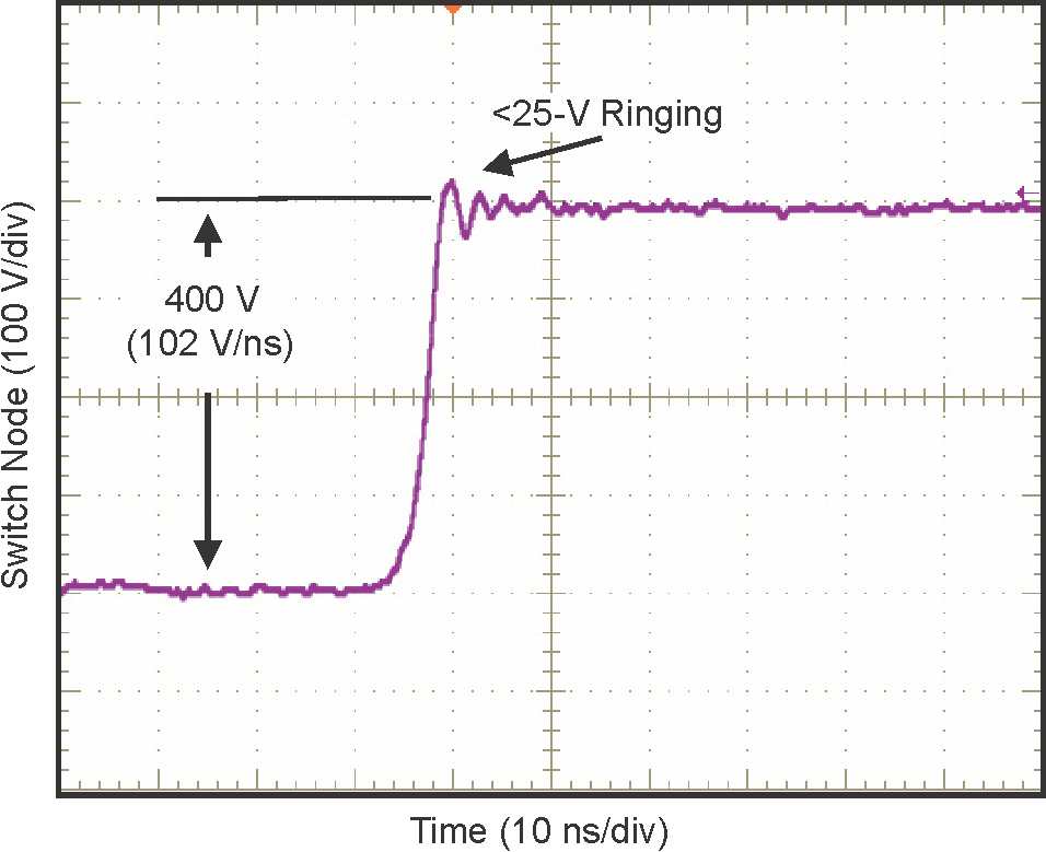
LMG342xR030 集成了一个硅驱动器,可实现高达 150 V/ns 的开关速度。与分立式硅栅极驱动器相比,TI 的集成式精密栅极偏置可实现更高的开关 SOA。这种集成特性与 TI 的低电感封装技术相结合,可在硬开关电源拓扑中提供干净的开关和超小的振铃。可调栅极驱动强度允许将压摆率控制在 20 V/ns 至 150 V/ns 之间,这可用于主动控制 EMI 并优化开关性能。LMG3425R030 包含理想二极管模式,该模式通过启用自适应死区时间控制功能来降低第三象限损耗。

高级电源管理功能包括数字温度报告和故障检测。GaN FET 的温度通过可变占空比 PWM 输出进行报告,这可简化器件加载管理。报告的故障包括过热、过流和 UVLO 监控。

器件信息
器件型号 封装 (1) 封装尺寸(标称值)
LMG3422R030 VQFN (54) 12.00mm x 12.00mm
LMG3425R030
如需了解所有可用封装,请参阅数据表末尾的可订购米6体育平台手机版_好二三四附录。
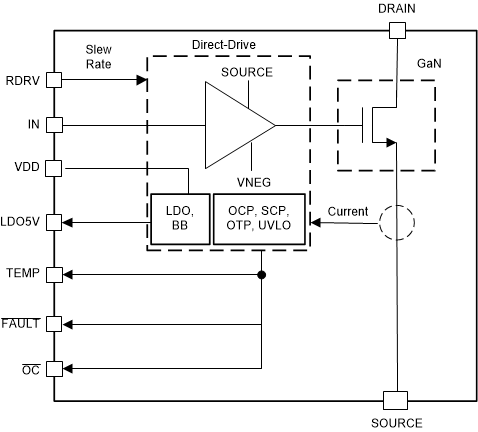
GUID-56727E62-3C5A-489B-87F9-87E74F3E3739-low.gif简化版方框图
GUID-3620467C-741C-47F7-9267-9B23B885C3BE-low.png高于 100 V/ns 时的开关性能