ZHCSDQ5A April   2015  – May 2015 LMH6401

PRODUCTION DATA.  

  1. 特性
  2. 应用
  3. 说明
  4. 修订历史记录
  5. Device Options
  6. Pin Configuration and Functions
  7. Specifications
    1. 7.1 Absolute Maximum Ratings
    2. 7.2 ESD Ratings
    3. 7.3 Recommended Operating Conditions
    4. 7.4 Thermal Information
    5. 7.5 Electrical Characteristics
    6. 7.6 SPI Timing Requirements
    7. 7.7 Typical Characteristics
  8. Parameter Measurement Information
    1. 8.1 Setup Diagrams
    2. 8.2 Output Measurement Reference Points
    3. 8.3 ATE Testing and DC Measurements
    4. 8.4 Frequency Response
    5. 8.5 Distortion
    6. 8.6 Noise Figure
    7. 8.7 Pulse Response, Slew Rate, and Overdrive Recovery
    8. 8.8 Power Down
    9. 8.9 VOCM Frequency Response
  9. Detailed Description
    1. 9.1 Overview
    2. 9.2 Functional Block Diagram
    3. 9.3 Feature Description
    4. 9.4 Device Functional Modes
      1. 9.4.1 Power-On Reset (POR)
      2. 9.4.2 Power-Down (PD)
      3. 9.4.3 Thermal Feedback Control
      4. 9.4.4 Gain Control
    5. 9.5 Programming
      1. 9.5.1 Details of the Serial Interface
      2. 9.5.2 Timing Diagrams
    6. 9.6 Register Maps
      1. 9.6.1 Revision ID (address = 0h, Read-Only) [default = 03h]
      2. 9.6.2 Product ID (address = 1h, Read-Only) [default = 00h]
      3. 9.6.3 Gain Control (address = 2h) [default = 20h]
      4. 9.6.4 Reserved (address = 3h) [default = 8Ch]
      5. 9.6.5 Thermal Feedback Gain Control (address = 4h) [default = 27h]
      6. 9.6.6 Thermal Feedback Frequency Control (address = 5h) [default = 45h]
  10. 10Application and Implementation
    1. 10.1 Application Information
      1. 10.1.1 Analog Input Characteristics
      2. 10.1.2 Analog Output Characteristics
        1. 10.1.2.1 Driving Capacitive Loads
      3. 10.1.3 Thermal Feedback Control
        1. 10.1.3.1 Step Response Optimization using Thermal Feedback Control
      4. 10.1.4 Thermal Considerations
    2. 10.2 Typical Application
      1. 10.2.1 Design Requirements
      2. 10.2.2 Detailed Design Procedure
        1. 10.2.2.1 Driving ADCs
          1. 10.2.2.1.1 SNR Considerations
          2. 10.2.2.1.2 SFDR Considerations
          3. 10.2.2.1.3 ADC Input Common-Mode Voltage Considerations—AC-Coupled Input
          4. 10.2.2.1.4 ADC Input Common-Mode Voltage Considerations—DC-Coupled Input
      3. 10.2.3 Application Curves
    3. 10.3 Do's and Don'ts
      1. 10.3.1 Do:
      2. 10.3.2 Don't:
  11. 11Power-Supply Recommendations
    1. 11.1 Single-Supply Operation
    2. 11.2 Split-Supply Operation
  12. 12Layout
    1. 12.1 Layout Guidelines
    2. 12.2 Layout Examples
  13. 13器件和文档支持
    1. 13.1 文档支持
      1. 13.1.1 相关文档 
    2. 13.2 社区资源
    3. 13.3 商标
    4. 13.4 静电放电警告
    5. 13.5 术语表
  14. 14机械、封装和可订购信息

封装选项

机械数据 (封装 | 引脚)
散热焊盘机械数据 (封装 | 引脚)
订购信息

6 Pin Configuration and Functions

RMZ Package
UQFN-16
Top View
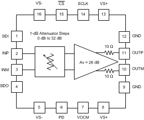
LMH6401 po_sbos730.gif

Pin Functions

PIN FUNCTION DESCRIPTION
NO. NAME
1 SDI Input Serial interface input data
2 INP Input Positive input pin
3 INM Input Negative input pin
4 SDO Output Serial interface output data
5 VS– Power Negative supply voltage
6 PD Input Power-down pin.
0 = amplifier enabled, 1 = amplifier disabled
7 VOCM Input Input pin to set amplifier output common-mode voltage
8 VS+ Power Positive supply voltage
9 GND Power Ground
10 OUTM Output Negative output pin
11 OUTP Output Positive output pin
12 GND Power Ground
13 VS+ Power Positive supply voltage
14 SCLK Input Serial interface clock
15 CS Input Chip select
16 VS– Power Negative supply voltage