ZHCSEN4E September 2015 – April 2018 LMK03318
PRODUCTION DATA.
- 1 特性
- 2 应用
- 3 说明
- 4 修订历史记录
- 5 说明 (续)
- 6 器件比较表
- 7 Pin Configuration and Functions
-
8 Specifications
- 8.1 Absolute Maximum Ratings
- 8.2 ESD Ratings
- 8.3 Recommended Operating Conditions
- 8.4 Thermal Information
- 8.5 Thermal Information
- 8.6 Electrical Characteristics - Power Supply
- 8.7 Pullable Crystal Characteristics (SECREF_P, SECREF_N)
- 8.8 Non-Pullable Crystal Characteristics (SECREF_P, SECREF_N)
- 8.9 Clock Input Characteristics (PRIREF_P/PRIREF_N, SECREF_P/SECREF_N)
- 8.10 VCO Characteristics
- 8.11 PLL Characteristics
- 8.12 1.8-V LVCMOS Output Characteristics (OUT[7:0])
- 8.13 LVCMOS Output Characteristics (STATUS[1:0])
- 8.14 Open-Drain Output Characteristics (STATUS[1:0])
- 8.15 AC-LVPECL Output Characteristics
- 8.16 AC-LVDS Output Characteristics
- 8.17 AC-CML Output Characteristics
- 8.18 HCSL Output Characteristics
- 8.19 Power-On Reset Characteristics
- 8.20 2-Level Logic Input Characteristics (HW_SW_CTRL, PDN, GPIO[5:0])
- 8.21 3-Level Logic Input Characteristics (REFSEL, GPIO[3:1])
- 8.22 Analog Input Characteristics (GPIO[5])
- 8.23 I2C-Compatible Interface Characteristics (SDA, SCL)
- 8.24 Typical 156.25-MHz Closed-Loop Output Phase Noise Characteristics
- 8.25 Typical 161.1328125-MHz Closed-Loop Output Phase Noise Characteristics
- 8.26 Closed-Loop Output Jitter Characteristics
- 8.27 PCIe Clock Output Jitter
- 8.28 Typical Power Supply Noise Rejection Characteristics
- 8.29 Typical Power-Supply Noise Rejection Characteristics
- 8.30 Typical Closed-Loop Output Spur Characteristics
- 8.31 Typical Characteristics
- 9 Parameter Measurement Information
-
10Detailed Description
- 10.1 Overview
- 10.2 Functional Block Diagram
- 10.3 Feature Description
- 10.4
Device Functional Modes
- 10.4.1 Smart Input MUX
- 10.4.2 Universal Input Buffer (PRI_REF, SEC_REF)
- 10.4.3 Crystal Input Interface (SEC_REF)
- 10.4.4 Reference Doubler
- 10.4.5 Reference Divider (R)
- 10.4.6 Input Divider (M)
- 10.4.7 Feedback Divider (N)
- 10.4.8 Phase Frequency Detector (PFD)
- 10.4.9 Charge Pump
- 10.4.10 Loop Filter
- 10.4.11 VCO Calibration
- 10.4.12 Fractional Circuitry
- 10.4.13 Post Divider
- 10.4.14 High-Speed Output MUX
- 10.4.15 High-Speed Output Divider
- 10.4.16 High-Speed Clock Outputs
- 10.4.17 Output Synchronization
- 10.4.18 Status Outputs
- 10.5 Programming
- 10.6
Register Maps
- 10.6.1 VNDRID_BY1 Register; R0
- 10.6.2 VNDRID_BY0 Register; R1
- 10.6.3 PRODID Register; R2
- 10.6.4 REVID Register; R3
- 10.6.5 PARTID Register; R4
- 10.6.6 PINMODE_SW Register; R8
- 10.6.7 PINMODE_HW Register; R9
- 10.6.8 SLAVEADR Register; R10
- 10.6.9 EEREV Register; R11
- 10.6.10 DEV_CTL Register; R12
- 10.6.11 INT_LIVE Register; R13
- 10.6.12 INT_MASK Register; R14
- 10.6.13 INT_FLAG_POL Register; R15
- 10.6.14 INT_FLAG Register; R16
- 10.6.15 INTCTL Register; R17
- 10.6.16 OSCCTL2 Register; R18
- 10.6.17 STATCTL Register; R19
- 10.6.18 MUTELVL1 Register; R20
- 10.6.19 MUTELVL2 Register; R21
- 10.6.20 OUT_MUTE Register; R22
- 10.6.21 STATUS_MUTE Register; R23
- 10.6.22 DYN_DLY Register; R24
- 10.6.23 REFDETCTL Register; R25
- 10.6.24 STAT0_INT Register; R27
- 10.6.25 STAT1 Register; R28
- 10.6.26 OSCCTL1 Register; R29
- 10.6.27 PWDN Register; R30
- 10.6.28 OUTCTL_0 Register; R31
- 10.6.29 OUTCTL_1 Register; R32
- 10.6.30 OUTDIV_0_1 Register; R33
- 10.6.31 OUTCTL_2 Register; R34
- 10.6.32 OUTCTL_3 Register; R35
- 10.6.33 OUTDIV_2_3 Register; R36
- 10.6.34 OUTCTL_4 Register; R37
- 10.6.35 OUTDIV_4 Register; R38
- 10.6.36 OUTCTL_5 Register; R39
- 10.6.37 OUTDIV_5 Register; R40
- 10.6.38 OUTCTL_6 Register; R41
- 10.6.39 OUTDIV_6 Register; R42
- 10.6.40 OUTCTL_7 Register; R43
- 10.6.41 OUTDIV_7 Register; R44
- 10.6.42 CMOSDIVCTRL Register; R45
- 10.6.43 CMOSDIV0 Register; R46
- 10.6.44 STATUS_SLEW Register; R49
- 10.6.45 IPCLKSEL Register; R50
- 10.6.46 IPCLKCTL Register; R51
- 10.6.47 PLL_RDIV Register; R52
- 10.6.48 PLL_MDIV Register; R53
- 10.6.49 PLL_CTRL0 Register; R56
- 10.6.50 PLL_CTRL1 Register; R57
- 10.6.51 PLL_NDIV_BY1 Register; R58
- 10.6.52 PLL_NDIV_BY0 Register; R59
- 10.6.53 PLL_FRACNUM_BY2 Register; R60
- 10.6.54 PLL_FRACNUM_BY1 Register; R61
- 10.6.55 PLL_FRACNUM_BY0 Register; R62
- 10.6.56 PLL_FRACDEN_BY2 Register; R63
- 10.6.57 PLL_FRACDEN_BY1 Register; R64
- 10.6.58 PLL_FRACDEN_BY0 Register; R65
- 10.6.59 PLL_MASHCTRL Register; R66
- 10.6.60 PLL_LF_R2 Register; R67
- 10.6.61 PLL_LF_C1 Register; R68
- 10.6.62 PLL_LF_R3 Register; R69
- 10.6.63 PLL_LF_C3 Register; R70
- 10.6.64 SEC_CTRL Register; R72
- 10.6.65 XO_MARGINING Register; R86
- 10.6.66 XO_OFFSET_GPIO5_STEP_1_BY1 Register; R88
- 10.6.67 XO_OFFSET_GPIO5_STEP_1_BY0 Register; R89
- 10.6.68 XO_OFFSET_GPIO5_STEP_2_BY1 Register; R90
- 10.6.69 XO_OFFSET_GPIO5_STEP_2_BY0 Register; R91
- 10.6.70 XO_OFFSET_GPIO5_STEP_3_BY1 Register; R92
- 10.6.71 XO_OFFSET_GPIO5_STEP_3_BY0 Register; R93
- 10.6.72 XO_OFFSET_GPIO5_STEP_4_BY1 Register; R94
- 10.6.73 XO_OFFSET_GPIO5_STEP_4_BY0 Register; R95
- 10.6.74 XO_OFFSET_GPIO5_STEP_5_BY1 Register; R96
- 10.6.75 XO_OFFSET_GPIO5_STEP_5_BY0 Register; R97
- 10.6.76 XO_OFFSET_GPIO5_STEP_6_BY1 Register; R98
- 10.6.77 XO_OFFSET_GPIO5_STEP_6_BY0 Register; R99
- 10.6.78 XO_OFFSET_GPIO5_STEP_7_BY1 Register; R100
- 10.6.79 XO_OFFSET_GPIO5_STEP_7_BY0 Register; R101
- 10.6.80 XO_OFFSET_GPIO5_STEP_8_BY1 Register; R102
- 10.6.81 XO_OFFSET_GPIO5_STEP_8_BY0 Register; R103
- 10.6.82 XO_OFFSET_SW_BY1 Register; R104
- 10.6.83 XO_OFFSET_SW_BY0 Register; R105
- 10.6.84 PLL_CTRL2 Register; R117
- 10.6.85 PLL_CTRL3 Register; R118
- 10.6.86 PLL_CALCTRL0 Register; R119
- 10.6.87 PLL_CALCTRL1 Register; R120
- 10.6.88 NVMCNT Register; R136
- 10.6.89 NVMCTL Register; R137
- 10.6.90 NVMLCRC Register; R138
- 10.6.91 MEMADR_BY1 Register; R139
- 10.6.92 MEMADR_BY0 Register; R140
- 10.6.93 NVMDAT Register; R141
- 10.6.94 RAMDAT Register; R142
- 10.6.95 ROMDAT Register; R143
- 10.6.96 NVMUNLK Register; R144
- 10.6.97 REGCOMMIT_PAGE Register; R145
- 10.6.98 XOCAPCTRL_BY1 Register; R199
- 10.6.99 XOCAPCTRL_BY0 Register; R200
- 10.6.100 EEPROM Map
- 11Application and Implementation
- 12Power Supply Recommendations
- 13Layout
- 14器件和文档支持
- 15机械、封装和可订购信息
13.2 Layout Example
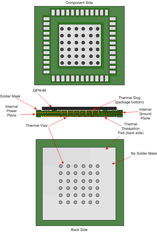
Figure 86 shows a PCB layout example showing the application of thermal design practices and low-inductance ground connection between the device DAP and the PCB. Connecting a 6 x 6 thermal via pattern and using multiple PCB ground layers (for example, 8- or 10-layer PCB) can help to reduce the junction-to-ambient thermal resistance, as indicated in the Thermal Information section. The 6 × 6 filled via pattern facilitates both considerations.
 Figure 86. 4-Layer PCB Thermal Layout Example for LMK03318 (8+ Layers Recommended)