ZHCSHN9A February 2018 – April 2018 LMK05028
PRODUCTION DATA.
- 1 特性
- 2 应用
- 3 说明
- 4 修订历史记录
- 5 说明 (续)
- 6 Pin Configuration and Functions
- 7 Specifications
- 8 Parameter Measurement Information
-
9 Detailed Description
- 9.1 Overview
- 9.2 Functional Block Diagrams
- 9.3
Feature Description
- 9.3.1 Oscillator Input (XO_P/N)
- 9.3.2 TCXO/OCXO Input (TCXO_IN)
- 9.3.3 Reference Inputs (INx_P/N)
- 9.3.4 Clock Input Interfacing and Termination
- 9.3.5 Reference Input Mux Selection
- 9.3.6 Hitless Switching
- 9.3.7 Gapped Clock Support on Reference Inputs
- 9.3.8 Input Clock and PLL Monitoring, Status, and Interrupts
- 9.3.9
PLL Channels
- 9.3.9.1 PLL Frequency Relationships
- 9.3.9.2 Analog PLL (APLL)
- 9.3.9.3 APLL XO Doubler
- 9.3.9.4 APLL Phase Frequency Detector (PFD) and Charge Pump
- 9.3.9.5 APLL Loop Filter
- 9.3.9.6 APLL Voltage Controlled Oscillator (VCO)
- 9.3.9.7 APLL VCO Post-Dividers (P1, P2)
- 9.3.9.8 APLL Fractional N Divider (N) With SDM
- 9.3.9.9 REF-DPLL Reference Divider (R)
- 9.3.9.10 TCXO/OCXO Input Doubler and M Divider
- 9.3.9.11 TCXO Mux
- 9.3.9.12 REF-DPLL and TCXO-DPLL Time-to-Digital Converter (TDC)
- 9.3.9.13 REF-DPLL and TCXO-DPLL Loop Filter
- 9.3.9.14 REF-DPLL and TCXO-DPLL Feedback Dividers
- 9.3.10 Output Clock Distribution
- 9.3.11 Output Channel Muxes
- 9.3.12 Output Dividers
- 9.3.13 Clock Outputs (OUTx_P/N)
- 9.3.14 Glitchless Output Clock Start-Up
- 9.3.15 Clock Output Interfacing and Termination
- 9.3.16 Output Synchronization (SYNC)
- 9.3.17 Zero-Delay Mode (ZDM) Configuration
- 9.3.18 PLL Cascading With Internal VCO Loopback
- 9.4 Device Functional Modes
- 9.5 Programming
- 9.6 Register Maps
- 10Application and Implementation
- 11Power Supply Recommendations
- 12Layout
- 13器件和文档支持
- 14机械、封装和可订购信息
9.2.1 PLL Architecture Overview
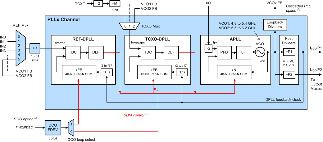
Figure 19 shows the 3-loop architecture implemented the same for both PLL channels with exception of the VCO frequency range. Each channel has three phase-locked loops with two digital PLLs (REF-DPLL and TCXO-DPLL) and one analog PLL (APLL) with integrated VCO. The REF-DPLL and TCXO-DPLL are each comprised of a time-to-digital converter (TDC), digital loop filter (DLF), feedback prescaler (PR), and 40-bit fractional feedback (FB) divider with sigma-delta-modulator (SDM or "MASH"). The APLL is comprised of a reference frequency doubler (×2), phase-frequency detector (PFD), loop filter (LF), fractional feedback (N) divider with SDM, and VCO.

Table 2 summarizes the PLL mode configuration options available in each channel. These modes support a wide range of use cases depending to the clock functionality and performance required in the application. Most applications will use 2-loop REF-DPLL or 3-loop mode for network synchronization clock features such as programmable loop bandwidth for jitter and wander attenuation, hitless switching, precise digital holdover, DCO frequency steering, and/or zero delay mode.
Table 2. PLL Mode Configuration Options
| PLL MODE | FRACTIONAL SDM ENABLED (SDM CONTROL FROM) | DCO MODE OPTION | FREE-RUN / HOLDOVER CLOCK | ||
|---|---|---|---|---|---|
| REF-DPLL | TCXO-DPLL | APLL | |||
| 1-Loop (APLL only) | – | – | Y (Free-run from XO) | – | XO |
| 2-Loop REF-DPLL | Y (DCO option) | – | Y (REF-DPLL) | REF-DPLL SDM | XO |
| 2-Loop TCXO-DPLL | – | Y (DCO option) | Y (TCXO-DPLL) | TCXO-DPLL SDM | TCXO |
| 3-Loop | Y (DCO option) | Y (REF-DPLL) | Y (TCXO-DPLL) | REF-DPLL SDM | TCXO |
The following sections describe the basic principle of operation for 2-loop and 3-loop modes. See PLL Operating Modes for more details on the PLL modes of operation including holdover.