ZHCSA29F October   2011  – June 2019 LMR24220

PRODUCTION DATA.  

  1. 特性
  2. 应用
  3. 说明
    1.     Device Images
      1.      典型应用
  4. 修订历史记录
  5. Pin Configuration and Functions
    1.     Pin Descriptions
  6. Specifications
    1. 6.1 Absolute Maximum Ratings
    2. 6.2 Recommended Operating Ratings
    3. 6.3 Electrical Characteristics
    4. 6.4 Typical Characteristics
  7. Detailed Description
    1. 7.1 Overview
    2. 7.2 Functional Block Diagram
    3. 7.3 Feature Description
      1. 7.3.1  CoT Control Circuit Overview
      2. 7.3.2  Start-up Regulator (VCC)
      3. 7.3.3  Regulation Comparator
      4. 7.3.4  Zero Coil Current Detect
      5. 7.3.5  Overvoltage Comparator
      6. 7.3.6  On-Time Timer, Shutdown
      7. 7.3.7  Current Limit
      8. 7.3.8  N-Channel MOSFET and Driver
      9. 7.3.9  Soft Start
      10. 7.3.10 Thermal Protection
  8. Application and Implementation
    1. 8.1 Application Information
    2. 8.2 Typical Application
      1. 8.2.1 Detailed Design Procedure
        1. 8.2.1.1 Custom Design With WEBENCH® Tools
        2. 8.2.1.2 External Components
      2. 8.2.2 Application Curve
  9. Layout
    1. 9.1 Layout Guidelines
    2. 9.2 Package Considerations
    3. 9.3 Thermal Derating
  10. 10器件和文档支持
    1. 10.1 器件支持
      1. 10.1.1 开发支持
        1. 10.1.1.1 使用 WEBENCH® 工具创建定制设计
    2. 10.2 接收文档更新通知
    3. 10.3 社区资源
    4. 10.4 商标
    5. 10.5 静电放电警告
    6. 10.6 Glossary
  11. 11机械、封装和可订购信息

封装选项

机械数据 (封装 | 引脚)
散热焊盘机械数据 (封装 | 引脚)
订购信息

On-Time Timer, Shutdown

The on-time of the LMR24220 main MOSFET is determined by the resistor RON and the input voltage VIN. It is calculated as follows:

Equation 4. LMR24220 30167623.gif

The inverse relationship of ton and VIN gives a nearly constant frequency as VIN is varied. Select RON so that the on-time at maximum VIN is greater than 150 ns. The on-timer has a limiter to ensure a minimum of 150 ns for ton. This limits the maximum operating frequency, which is governed by Equation 5:

Equation 5. LMR24220 30167624.gif

The LMR24220 can be remotely shutdown by pulling the voltage of the EN pin below 1 V. In this shutdown mode, the SS pin is internally grounded, the on-timer is disabled, and bias currents are reduced. Releasing the EN pin allows normal operation to resume because the EN pin is internally pulled up.
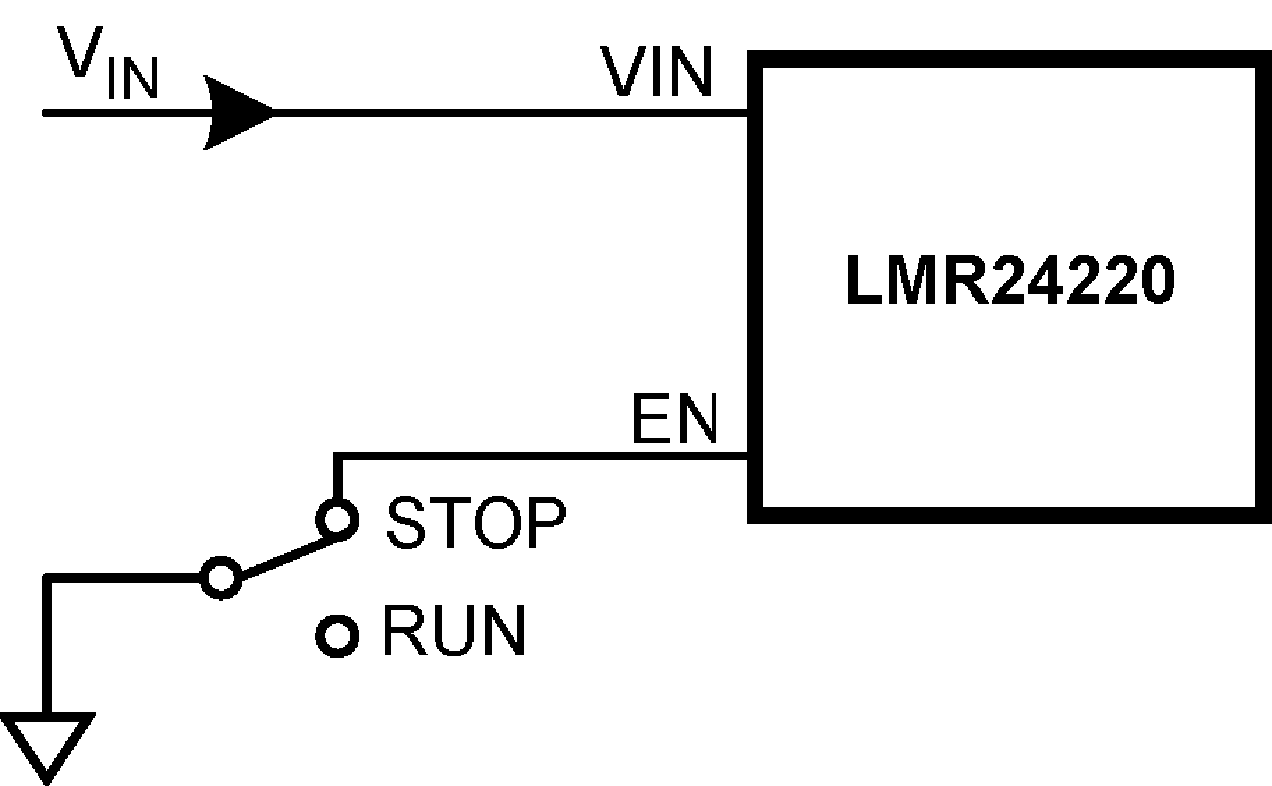
LMR24220 30167625.pngFigure 17. Shutdown Implementation