ZHCSGY9B July 2017 – March 2018 LMS3655
PRODUCTION DATA.
- 1 特性
- 2 应用
- 3 说明
- 4 修订历史记录
- 5 Device Comparison Table
- 6 Pin Configuration and Functions
- 7 Specifications
- 8 Detailed Description
-
9 Application and Implementation
- 9.1 Application Information
- 9.2
Typical Applications
- 9.2.1 General Application
- 9.2.2 Adjustable 5-V Output
- 9.2.3 Adjustable 3.3-V Output
- 9.2.4 6-V Adjustable Output
- 9.3 Do's and Don't's
- 10Power Supply Recommendations
- 11Layout
- 12器件和文档支持
- 13机械、封装和可订购信息
9.2.1 General Application
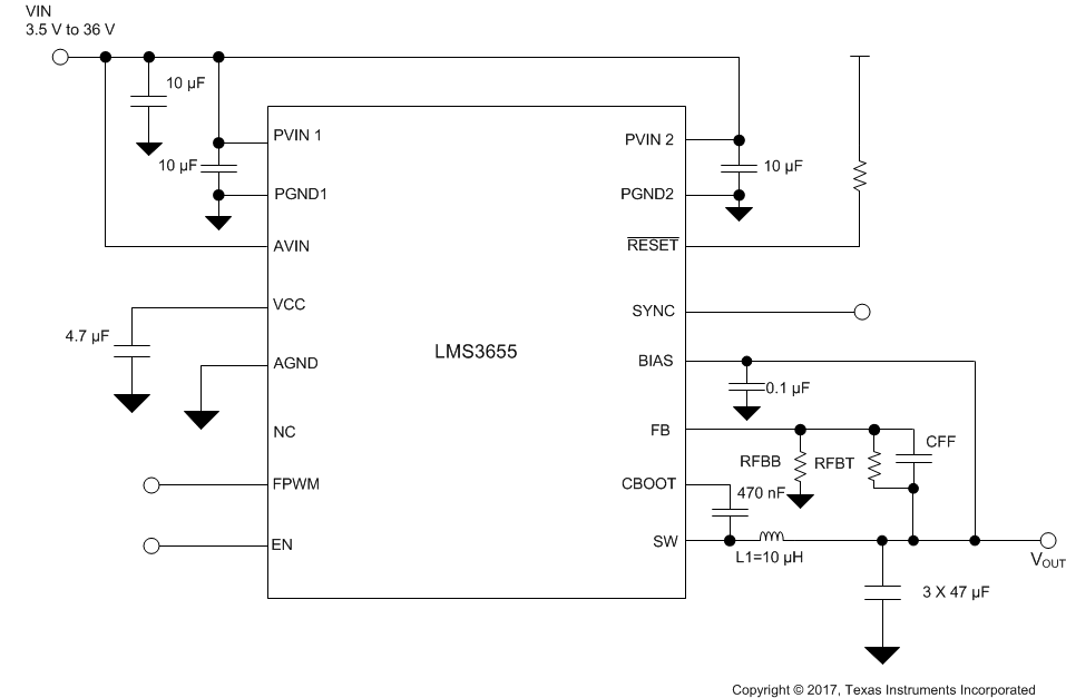
Figure 20 shows a general application schematic. FPWM, SYNC, and EN are digital inputs. RESET is an open-drain output.
- The FPWM pin can be connected to GND to enable light-load PFM operation. Select this option if current consumption at light load is critical. The pin can be connected to VCC or VIN for forced 400-kHz operation. Select this option if constant switching frequency is critical. The pin can also be driven by an external signal and can be toggled while the part is in operation (by an MCU, for example). Refer to the Device Functional Modes for more details on the operation and signal requirements of the FPWM pin.
- The SYNC pin can be used to control the switching frequency and the phase of the converter. If the function is not needed, tie the SYNC pin to GND, VCC, or VIN.
- The RESET pin can be left floating or tied to ground if the function is not required. If the function is needed, the pin must be connected to a DC rail through a pullup resistor (100 kΩ is the typical recommended value). Check RESET Flag Output for the details of the RESET pin function.
- Connect the output to the FB pin through a voltage divider. See Detailed Design Procedure for details on component selection.
- The BIAS pin can be connected directly to the output voltage. In applications that can experience inductive shorts (such as cases with long leads on the output), a 3 Ω or so is necessary between the output and the BIAS pin, and a small capacitor to GND is necessary close to the BIAS pin (CBIAS). Alternatively, a Schottky diode can be connected between OUT and GND to limit the negative voltage that can arise on the output during inductive shorts. In addition, BIAS can also be connected to an external rail if necessary and if available. The typical current into the bias pin is 15 mA when the device is operating in PWM mode at 400 kHz.
- Power components must be chosen carefully for proper operation of the converter. Detailed Design Procedure discusses the details of the process of choosing the input capacitors, output capacitors, and inductor for the application.
 Figure 20. General Application Circuit