ZHCSH13B October 2017 – January 2019 LMX2572
PRODUCTION DATA.
- 1 特性
- 2 应用
- 3 说明
- 4 修订历史记录
- 5 Pin Configuration and Functions
- 6 Specifications
-
7 Detailed Description
- 7.1 Overview
- 7.2 Functional Block Diagram
- 7.3
Feature Description
- 7.3.1 Reference Oscillator Input
- 7.3.2 Reference Path
- 7.3.3 PLL Phase Detector and Charge Pump
- 7.3.4 PLL N Divider and Fractional Circuitry
- 7.3.5 Voltage-Controlled Oscillator
- 7.3.6 Channel Divider
- 7.3.7 Output Buffer
- 7.3.8 Lock Detect
- 7.3.9 Register Readback
- 7.3.10 Powerdown
- 7.3.11 Phase Synchronization
- 7.3.12 Phase Adjustment
- 7.3.13 Ramping Function
- 7.3.14 SYSREF
- 7.3.15 FSK Modulation
- 7.4 Device Functional Modes
- 7.5 Programming
- 7.6
Register Maps
- 7.6.1 Register R0 (offset = 00h) [reset = 221Ch]
- 7.6.2 Register R1 (offset = 01h) [reset = 0808h]
- 7.6.3 Register R2 (offset = 02h) [reset = 0500h]
- 7.6.4 Register R3 (offset = 03h) [reset = 0782h]
- 7.6.5 Register R4 (offset = 04h) [reset = 0A43h]
- 7.6.6 Register R5 (offset = 05h) [reset = 30C8h]
- 7.6.7 Register R6 (offset = 06h) [reset = C802h]
- 7.6.8 Register R7 (offset = 07h) [reset = 00B2h]
- 7.6.9 Register R8 (offset = 08h) [reset = 2000h]
- 7.6.10 Register R9 (offset = 09h) [reset = 0004h]
- 7.6.11 Register R10 (offset = 0Ah) [reset = 10F8h]
- 7.6.12 Register R11 (offset = 0Bh) [reset = B018h]
- 7.6.13 Register R12 (offset = 0Ch) [reset = 5001h]
- 7.6.14 Register R13 (offset = 0Dh) [reset = 4000h]
- 7.6.15 Register R14 (offset = 0Eh) [reset = 1840h]
- 7.6.16 Register R15 (offset = 0Fh) [reset = 060Eh]
- 7.6.17 Register R16 (offset = 10h) [reset = 0080h]
- 7.6.18 Register R17 (offset = 11h) [reset = 0096h]
- 7.6.19 Register R18 (offset = 12h) [reset = 0064h]
- 7.6.20 Register R19 (offset = 13h) [reset = 27B7h]
- 7.6.21 Register R20 (offset = 14h) [reset = 3048h]
- 7.6.22 Register R21 (offset = 15h) [reset = 0409h]
- 7.6.23 Register R22 (offset = 16h) [reset = 0001h]
- 7.6.24 Register R23 (offset = 17h) [reset = 007Ch]
- 7.6.25 Register R24 (offset = 18h) [reset = 071Ah]
- 7.6.26 Register R25 (offset = 19h) [reset = 0624h]
- 7.6.27 Register R26 (offset = 1Ah) [reset = 0808h]
- 7.6.28 Register R27 (offset = 1Bh) [reset = 0002h]
- 7.6.29 Register R28 (offset = 1Ch) [reset = 0488h]
- 7.6.30 Register R29 (offset = 1Dh) [reset = 18C6h]
- 7.6.31 Register R30 (offset = 1Eh) [reset = 18C6h]
- 7.6.32 Register R31 (offset = 1Fh) [reset = C3E6h]
- 7.6.33 Register R32 (offset = 20h) [reset = 05BFh]
- 7.6.34 Register R33 (offset = 21h) [reset = 1E01h]
- 7.6.35 Register R34 (offset = 22h) [reset = 0010h]
- 7.6.36 Register R35 (offset = 23h) [reset = 0004h]
- 7.6.37 Register R36 (offset = 24h) [reset = 0028h]
- 7.6.38 Register R37 (offset = 25h) [reset = 0205h]
- 7.6.39 Register R38 (offset = 26h) [reset = FFFFh]
- 7.6.40 Register R39 (offset = 27h) [reset = FFFFh]
- 7.6.41 Register R40 (offset = 28h) [reset = 0000h]
- 7.6.42 Register R41 (offset = 29h) [reset = 0000h]
- 7.6.43 Register R42 (offset = 2Ah) [reset = 0000h]
- 7.6.44 Register R43 (offset = 2Bh) [reset = 0000h]
- 7.6.45 Register R44 (offset = 2Ch) [reset = 22A2h]
- 7.6.46 Register R45 (offset = 2Dh) [reset = C622h]
- 7.6.47 Register R46 (offset = 2Eh) [reset = 07F0h]
- 7.6.48 Register R47 (offset = 2Fh) [reset = 0300h]
- 7.6.49 Register R48 (offset = 30h) [reset = 03E0h]
- 7.6.50 Register R49 (offset = 31h) [reset = 4180h]
- 7.6.51 Register R50 (offset = 32h) [reset = 0080h]
- 7.6.52 Register R51 (offset = 33h) [reset = 0080h]
- 7.6.53 Register R52 (offset = 34h) [reset = 0420h]
- 7.6.54 Register R53 (offset = 35h) [reset = 0000h]
- 7.6.55 Register R54 (offset = 36h) [reset = 0000h]
- 7.6.56 Register R55 (offset = 37h) [reset = 0000h]
- 7.6.57 Register R56 (offset = 38h) [reset = 0000h]
- 7.6.58 Register R57 (offset = 39h) [reset = 0000h]
- 7.6.59 Register R58 (offset = 3Ah) [reset = 8001h]
- 7.6.60 Register R59 (offset = 3Bh) [reset = 0001h]
- 7.6.61 Register R60 (offset = 3Ch) [reset = 03E8h]
- 7.6.62 Register R61 (offset = 3Dh) [reset = 00A8h]
- 7.6.63 Register R62 (offset = 3Eh) [reset = 00AFh]
- 7.6.64 Register R63 (offset = 3Fh) [reset = 0000h]
- 7.6.65 Register R64 (offset = 40h) [reset = 1388h]
- 7.6.66 Register R65 (offset = 41h) [reset = 0000h]
- 7.6.67 Register R66 (offset = 42h) [reset = 01F4h]
- 7.6.68 Register R67 (offset = 43h) [reset = 0000h]
- 7.6.69 Register R68 (offset = 44h) [reset = 03E8h]
- 7.6.70 Register R69 (offset = 45h) [reset = 0000h]
- 7.6.71 Register R70 (offset = 46h) [reset = C350h]
- 7.6.72 Register R71 (offset = 47h) [reset = 0080h]
- 7.6.73 Register R72 (offset = 48h) [reset = 0001h]
- 7.6.74 Register R73 (offset = 49h) [reset = 003Fh]
- 7.6.75 Register R74 (offset = 4Ah) [reset = 0000h]
- 7.6.76 Register R75 (offset = 4Bh) [reset = 0800h]
- 7.6.77 Register R76 (offset = 4Ch) [reset = 000Ch]
- 7.6.78 Register R77 (offset = 4Dh) [reset = 0000h]
- 7.6.79 Register R78 (offset = 4Eh) [reset = 0064h]
- 7.6.80 Register R79 (offset = 4Fh) [reset = 0000h]
- 7.6.81 Register R80 (offset = 50h) [reset = 0000h]
- 7.6.82 Register R81 (offset = 51h) [reset = 0000h]
- 7.6.83 Register R82 (offset = 52h) [reset = 0000h]
- 7.6.84 Register R83 (offset = 53h) [reset = 0000h]
- 7.6.85 Register R84 (offset = 54h) [reset = 0000h]
- 7.6.86 Register R85 (offset = 55h) [reset = 0000h]
- 7.6.87 Register R86 (offset = 56h) [reset = 0000h]
- 7.6.88 Register R87 (offset = 57h) [reset = 0000h]
- 7.6.89 Register R88 (offset = 58h) [reset = 0000h]
- 7.6.90 Register R89 (offset = 59h) [reset = 0000h]
- 7.6.91 Register R90 (offset = 5Ah) [reset = 0000h]
- 7.6.92 Register R91 (offset = 5Bh) [reset = 0000h]
- 7.6.93 Register R92 (offset = 5Ch) [reset = 0000h]
- 7.6.94 Register R93 (offset = 5Dh) [reset = 0000h]
- 7.6.95 Register R94 (offset = 5Eh) [reset = 0000h]
- 7.6.96 Register R95 (offset = 5Fh) [reset = 0000h]
- 7.6.97 Register R96 (offset = 60h) [reset = 0000h]
- 7.6.98 Register R97 (offset = 61h) [reset = 0000h]
- 7.6.99 Register R98 (offset = 62h) [reset = 0000h]
- 7.6.100 Register R99 (offset = 63h) [reset = 0000h]
- 7.6.101 Register R100 (offset = 64h) [reset = 0000h]
- 7.6.102 Register R101 (offset = 65h) [reset = 0000h]
- 7.6.103 Register R102 (offset = 66h) [reset = 0000h]
- 7.6.104 Register R103 (offset = 67h) [reset = 0000h]
- 7.6.105 Register R104 (offset = 68h) [reset = 0000h]
- 7.6.106 Register R105 (offset = 69h) [reset = 4440h]
- 7.6.107 Register R106 (offset = 6Ah) [reset = 0007h]
- 7.6.108 Register R107 (offset = 6Bh) [reset = 0000h]
- 7.6.109 Register R108 (offset = 6Ch) [reset = 0000h]
- 7.6.110 Register R109 (offset = 6Dh) [reset = 0000h]
- 7.6.111 Register R110 (offset = 6Eh) [reset = 0000h]
- 7.6.112 Register R111 (offset = 6Fh) [reset = 0000h]
- 7.6.113 Register R112 (offset = 70h) [reset = 0000h]
- 7.6.114 Register R113 (offset = 71h) [reset = 0000h]
- 7.6.115 Register R114 (offset = 72h) [reset = 7800h]
- 7.6.116 Register R115 (offset = 73h) [reset = 0000h]
- 7.6.117 Register R116 (offset = 74h) [reset = 0000h]
- 7.6.118 Register R117 (offset = 75h) [reset = 0000h]
- 7.6.119 Register R118 (offset = 76h) [reset = 0000h]
- 7.6.120 Register R119 (offset = 77h) [reset = 0000h]
- 7.6.121 Register R120 (offset = 78h) [reset = 0000h]
- 7.6.122 Register R121 (offset = 79h) [reset = 0000h]
- 7.6.123 Register R122 (offset = 7Ah) [reset = 0000h]
- 7.6.124 Register R123 (offset = 7Bh) [reset = 0000h]
- 7.6.125 Register R124 (offset = 7Ch) [reset = 0000h]
- 7.6.126 Register R125 (offset = 7Dh) [reset = 2288h]
-
8 Application and Implementation
- 8.1 Application Information
- 8.2 Typical Application
- 8.3 Do's and Don'ts
- 9 Power Supply Recommendations
- 10Layout
- 11器件和文档支持
- 12机械、封装和可订购信息
8.1.6 Application for SYNC
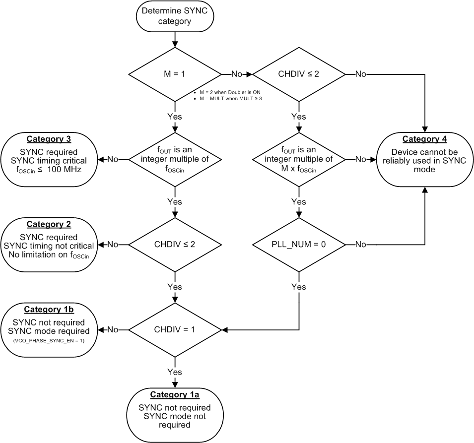
The requirements for SYNC depend on certain setup conditions. In cases where the SYNC is not timing critical, the setup can be done through software by toggling the VCO_PHASE_SYNC_EN bit from 0 to 1. When the SYNC is timing critical, then setup must be done through the SYNC pin and the setup and hold times for the OSCin pin are critical.
 Figure 170. SYNC Category
 The procedure for using SYNC in different SYNC categories is shown in Table 137.
Table 137. Procedure for Using SYNC
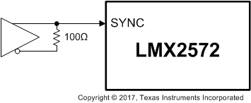
Set these bits to drive the SYNC pin with a LVDS signal:
- Set INPIN_FMT to 1 or 3 to enable LVDS input
- Set INPIN_LVL to one of the options
- Set INPIN_HYST, if necessary
The LVDS driver that is driving the SYNC pin should be configured as shown in Figure 171:
 Figure 171. Driving SYNC Pin With Differential Signal