ZHCSIA2 May 2018 LMX2572LP
PRODUCTION DATA.
- 1 特性
- 2 应用
- 3 说明
- 4 修订历史记录
- 5 Pin Configuration and Functions
- 6 Specifications
-
7 Detailed Description
- 7.1 Overview
- 7.2 Functional Block Diagram
- 7.3
Feature Description
- 7.3.1 Reference Oscillator Input
- 7.3.2 Reference Path
- 7.3.3 PLL Phase Detector and Charge Pump
- 7.3.4 PLL N Divider and Fractional Circuitry
- 7.3.5 Voltage-Controlled Oscillator
- 7.3.6 Channel Divider
- 7.3.7 Output Buffer
- 7.3.8 Lock Detect
- 7.3.9 Register Readback
- 7.3.10 Powerdown
- 7.3.11 Phase Synchronization
- 7.3.12 Phase Adjustment
- 7.3.13 Ramping Function
- 7.3.14 FSK Modulation
- 7.4 Device Functional Modes
- 7.5 Programming
- 7.6
Register Maps
- 7.6.1 Register R0 (offset = 00h) [reset = 221Ch]
- 7.6.2 Register R1 (offset = 01h) [reset = 0808h]
- 7.6.3 Register R2 (offset = 02h) [reset = 0500h]
- 7.6.4 Register R3 (offset = 03h) [reset = 0782h]
- 7.6.5 Register R4 (offset = 04h) [reset = 0A43h]
- 7.6.6 Register R5 (offset = 05h) [reset = 30C8h]
- 7.6.7 Register R6 (offset = 06h) [reset = C802h]
- 7.6.8 Register R7 (offset = 07h) [reset = 00B2h]
- 7.6.9 Register R8 (offset = 08h) [reset = 2000h]
- 7.6.10 Register R9 (offset = 09h) [reset = 0004h]
- 7.6.11 Register R10 (offset = 0Ah) [reset = 10F8h]
- 7.6.12 Register R11 (offset = 0Bh) [reset = B018h]
- 7.6.13 Register R12 (offset = 0Ch) [reset = 5001h]
- 7.6.14 Register R13 (offset = 0Dh) [reset = 4000h]
- 7.6.15 Register R14 (offset = 0Eh) [reset = 1840h]
- 7.6.16 Register R15 (offset = 0Fh) [reset = 060Eh]
- 7.6.17 Register R16 (offset = 10h) [reset = 0080h]
- 7.6.18 Register R17 (offset = 11h) [reset = 0096h]
- 7.6.19 Register R18 (offset = 12h) [reset = 0064h]
- 7.6.20 Register R19 (offset = 13h) [reset = 27B7h]
- 7.6.21 Register R20 (offset = 14h) [reset = 3048h]
- 7.6.22 Register R21 (offset = 15h) [reset = 0409h]
- 7.6.23 Register R22 (offset = 16h) [reset = 0001h]
- 7.6.24 Register R23 (offset = 17h) [reset = 007Ch]
- 7.6.25 Register R24 (offset = 18h) [reset = 071Ah]
- 7.6.26 Register R25 (offset = 19h) [reset = 0624h]
- 7.6.27 Register R26 (offset = 1Ah) [reset = 0808h]
- 7.6.28 Register R27 (offset = 1Bh) [reset = 0002h]
- 7.6.29 Register R28 (offset = 1Ch) [reset = 0488h]
- 7.6.30 Register R29 (offset = 1Dh) [reset = 18C6h]
- 7.6.31 Register R30 (offset = 1Eh) [reset = 18C6h]
- 7.6.32 Register R31 (offset = 1Fh) [reset = C3E6h]
- 7.6.33 Register R32 (offset = 20h) [reset = 05BFh]
- 7.6.34 Register R33 (offset = 21h) [reset = 1E01h]
- 7.6.35 Register R34 (offset = 22h) [reset = 0010h]
- 7.6.36 Register R35 (offset = 23h) [reset = 0004h]
- 7.6.37 Register R36 (offset = 24h) [reset = 0028h]
- 7.6.38 Register R37 (offset = 25h) [reset = 0205h]
- 7.6.39 Register R38 (offset = 26h) [reset = FFFFh]
- 7.6.40 Register R39 (offset = 27h) [reset = FFFFh]
- 7.6.41 Register R40 (offset = 28h) [reset = 0000h]
- 7.6.42 Register R41 (offset = 29h) [reset = 0000h]
- 7.6.43 Register R42 (offset = 2Ah) [reset = 0000h]
- 7.6.44 Register R43 (offset = 2Bh) [reset = 0000h]
- 7.6.45 Register R44 (offset = 2Ch) [reset = 08A2h]
- 7.6.46 Register R45 (offset = 2Dh) [reset = C608h]
- 7.6.47 Register R46 (offset = 2Eh) [reset = 07F0h]
- 7.6.48 Register R47 (offset = 2Fh) [reset = 0300h]
- 7.6.49 Register R48 (offset = 30h) [reset = 03E0h]
- 7.6.50 Register R49 (offset = 31h) [reset = 4180h]
- 7.6.51 Register R50 (offset = 32h) [reset = 0080h]
- 7.6.52 Register R51 (offset = 33h) [reset = 0080h]
- 7.6.53 Register R52 (offset = 34h) [reset = 0420h]
- 7.6.54 Register R53 (offset = 35h) [reset = 0000h]
- 7.6.55 Register R54 (offset = 36h) [reset = 0000h]
- 7.6.56 Register R55 (offset = 37h) [reset = 0000h]
- 7.6.57 Register R56 (offset = 38h) [reset = 0000h]
- 7.6.58 Register R57 (offset = 39h) [reset = 0000h]
- 7.6.59 Register R58 (offset = 3Ah) [reset = 8001h]
- 7.6.60 Register R59 (offset = 3Bh) [reset = 0001h]
- 7.6.61 Register R60 (offset = 3Ch) [reset = 03E8h]
- 7.6.62 Register R61 (offset = 3Dh) [reset = 00A8h]
- 7.6.63 Register R62 (offset = 3Eh) [reset = 00AFh]
- 7.6.64 Register R63 (offset = 3Fh) [reset = 0000h]
- 7.6.65 Register R64 (offset = 40h) [reset = 1388h]
- 7.6.66 Register R65 (offset = 41h) [reset = 0000h]
- 7.6.67 Register R66 (offset = 42h) [reset = 01F4h]
- 7.6.68 Register R67 (offset = 43h) [reset = 0000h]
- 7.6.69 Register R68 (offset = 44h) [reset = 03E8h]
- 7.6.70 Register R69 (offset = 45h) [reset = 0000h]
- 7.6.71 Register R70 (offset = 46h) [reset = C350h]
- 7.6.72 Register R71 (offset = 47h) [reset = 0080h]
- 7.6.73 Register R72 (offset = 48h) [reset = 0001h]
- 7.6.74 Register R73 (offset = 49h) [reset = 003Fh]
- 7.6.75 Register R74 (offset = 4Ah) [reset = 0000h]
- 7.6.76 Register R75 (offset = 4Bh) [reset = 0800h]
- 7.6.77 Register R76 (offset = 4Ch) [reset = 000Ch]
- 7.6.78 Register R77 (offset = 4Dh) [reset = 0000h]
- 7.6.79 Register R78 (offset = 4Eh) [reset = 0064h]
- 7.6.80 Register R79 (offset = 4Fh) [reset = 0000h]
- 7.6.81 Register R80 (offset = 50h) [reset = 0000h]
- 7.6.82 Register R81 (offset = 51h) [reset = 0000h]
- 7.6.83 Register R82 (offset = 52h) [reset = 0000h]
- 7.6.84 Register R83 (offset = 53h) [reset = 0000h]
- 7.6.85 Register R84 (offset = 54h) [reset = 0000h]
- 7.6.86 Register R85 (offset = 55h) [reset = 0000h]
- 7.6.87 Register R86 (offset = 56h) [reset = 0000h]
- 7.6.88 Register R87 (offset = 57h) [reset = 0000h]
- 7.6.89 Register R88 (offset = 58h) [reset = 0000h]
- 7.6.90 Register R89 (offset = 59h) [reset = 0000h]
- 7.6.91 Register R90 (offset = 5Ah) [reset = 0000h]
- 7.6.92 Register R91 (offset = 5Bh) [reset = 0000h]
- 7.6.93 Register R92 (offset = 5Ch) [reset = 0000h]
- 7.6.94 Register R93 (offset = 5Dh) [reset = 0000h]
- 7.6.95 Register R94 (offset = 5Eh) [reset = 0000h]
- 7.6.96 Register R95 (offset = 5Fh) [reset = 0000h]
- 7.6.97 Register R96 (offset = 60h) [reset = 0000h]
- 7.6.98 Register R97 (offset = 61h) [reset = 0000h]
- 7.6.99 Register R98 (offset = 62h) [reset = 0000h]
- 7.6.100 Register R99 (offset = 63h) [reset = 0000h]
- 7.6.101 Register R100 (offset = 64h) [reset = 0000h]
- 7.6.102 Register R101 (offset = 65h) [reset = 0000h]
- 7.6.103 Register R102 (offset = 66h) [reset = 0000h]
- 7.6.104 Register R103 (offset = 67h) [reset = 0000h]
- 7.6.105 Register R104 (offset = 68h) [reset = 0000h]
- 7.6.106 Register R105 (offset = 69h) [reset = 4440h]
- 7.6.107 Register R106 (offset = 6Ah) [reset = 0007h]
- 7.6.108 Register R107 (offset = 6Bh) [reset = 0000h]
- 7.6.109 Register R108 (offset = 6Ch) [reset = 0000h]
- 7.6.110 Register R109 (offset = 6Dh) [reset = 0000h]
- 7.6.111 Register R110 (offset = 6Eh) [reset = 0000h]
- 7.6.112 Register R111 (offset = 6Fh) [reset = 0000h]
- 7.6.113 Register R112 (offset = 70h) [reset = 0000h]
- 7.6.114 Register R113 (offset = 71h) [reset = 0000h]
- 7.6.115 Register R114 (offset = 72h) [reset = 7800h]
- 7.6.116 Register R115 (offset = 73h) [reset = 0000h]
- 7.6.117 Register R116 (offset = 74h) [reset = 0000h]
- 7.6.118 Register R117 (offset = 75h) [reset = 0000h]
- 7.6.119 Register R118 (offset = 76h) [reset = 0000h]
- 7.6.120 Register R119 (offset = 77h) [reset = 0000h]
- 7.6.121 Register R120 (offset = 78h) [reset = 0000h]
- 7.6.122 Register R121 (offset = 79h) [reset = 0000h]
- 7.6.123 Register R122 (offset = 7Ah) [reset = 0000h]
- 7.6.124 Register R123 (offset = 7Bh) [reset = 0000h]
- 7.6.125 Register R124 (offset = 7Ch) [reset = 0000h]
- 7.6.126 Register R125 (offset = 7Dh) [reset = 0820h]
-
8 Application and Implementation
- 8.1 Application Information
- 8.2 Typical Application
- 8.3 Do's and Don'ts
- 9 Power Supply Recommendations
- 10Layout
- 11器件和文档支持
- 12机械、封装和可订购信息
8.1.8 Application for FSK
In fractional mode, the finest delta frequency difference between two programmable output frequencies is equal to Equation 7:
In other words, when the fractional numerator is incremented by 1 (one step), the output frequency will change by Δfmin. A two steps increment will therefore change the frequency by 2 × Δfmin.
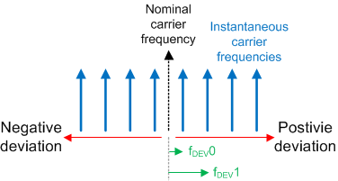
In FSK operation, the instantaneous carrier frequency is kept changing among some pre-defined frequencies. In general, the instantaneous carrier frequency is defined as a certain frequency deviation from the nominal carrier frequency. The frequency deviation could be positive and negative.
 Figure 163. General FSK Definition
 Equation 8 and Equation 9 define the number of steps required for the desired frequency deviation with respect to the nominal carrier frequency output. Assume ΔfDEV is the frequency deviation,
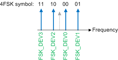
In FSK SPI mode, registers R116 – R123 are used to store the desired FSK steps as defined in Equation 8 and Equation 9. The order of the registers, 0 to 7, depends on the application system. A typical 4FSK definition is shown in Figure 164. In this case, the FSK_DEV0 and FSK_DEV1 are calculated using Equation 8, while the FSK_DEV2 and FSK_DEV3 are calculated using Equation 9.
 Figure 164. Typical 4FSK Definition
 FSK SPI mode assumes the user knows which symbol to send. The user can directly write to FSK_SPI_DEV_SEL to select the desired frequency deviation. For example, to enable the device to support 4FSK modulation in FSK SPI mode, set:
- FSK_MODE_SEL = 2 (FSK SPI)
- FSK_SPI_LEVEL = 2 (4FSK)
- FSK_EN = 1
Table 139. FSK SPI Mode Example
| DESIRED SYMBOL | WRITE REGISTER FSK_SPI_DEV_SEL | REGISTER SELECTED |
|---|---|---|
| 10 | 2 | FSK_DEV2 |
| 11 | 3 | FSK_DEV3 |
| 10 | 2 | FSK_DEV2 |
| 11 | 3 | FSK_DEV3 |
| 01 | 1 | FSK_DEV1 |
| 00 | 0 | FSK_DEV0 |
| … | … | … |
FSK SPI mode supports up to eight levels of FSK. To support an arbitrary-level FSK, use FSK SPI FAST mode. Constructing pulse-shaping FSK modulation by over-sampling the FSK modulation waveform is one of the used cases of this mode.
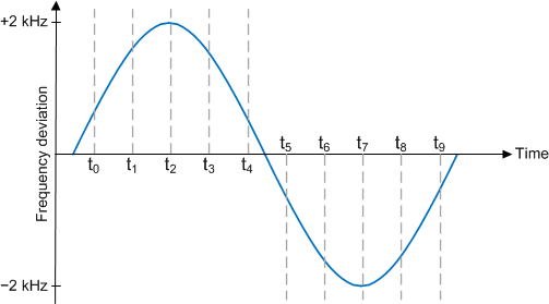
Analog-FM modulation can also be produced in this mode. For example, with a 1-kHz sine wave modulation signal with peak frequency deviation of ±2 kHz, the signal can be oversampled, say 10 times. Each sample point corresponding to a scaled frequency deviation.
 Figure 165. Oversampling Modulation Signal
 In FSK SPI FAST mode, write the desired FSK steps directly to FSK_SPI_FAST_DEV. To enable this mode, set:
- FSK_MODE_SEL = 3 (FSK SPI FAST)
- FSK_EN = 1
Table 140. FSK SPI FAST Mode Example
| TIME | FREQUENCY DEVIATION (Hz) | CORRESPONDING FSK STEPS(1) | BINARY EQUIVALENT | WRITE TO FSK_SPI_FAST_DEV |
|---|---|---|---|---|
| t0 | 618.034 | 396 | 0000 0001 1000 1100 | 396 |
| t1 | 1618.034 | 1036 | 0000 0100 0000 1100 | 1036 |
| t2 | 2000 | 1280 | 0000 0101 0000 0000 | 1280 |
| … | … | … | … | … |
| t6 | –1618.034 | 64500 | 1111 1011 1111 0011 | 64500 |
| t7 | –2000 | 64256 | 1111 1010 1111 1111 | 64256 |
| … | … | … | … | … |
Block Programming is possible with FSK SPI FAST mode programming as long as ADD_HOLD = 1, which will freeze the register address after the first register write. The same programming sequent as shown in Figure 27 applies.
In FSK I2S mode, clock in the desired binary format FSK steps in the I2S interface.
 Figure 166. FSK I2S Mode Example
 To enable FSK I2S mode, set
- INPIN_IGNORE = 0
- FSK_MODE_SEL = 1 (FSK I2S)
- FSK_EN = 1