ZHCSET9B January 2016 – June 2018 LP8758-E0
PRODUCTION DATA.
- 1 特性
- 2 应用
- 3 说明
- 4 修订历史记录
- 5 Pin Configuration and Functions
- 6 Specifications
-
7 Detailed Description
- 7.1 Overview
- 7.2 Functional Block Diagram
- 7.3 Feature Description
- 7.4 Device Functional Modes
- 7.5 Programming
- 7.6
Register Maps
- 7.6.1
Register Descriptions
- 7.6.1.1 OTP_REV
- 7.6.1.2 BUCK0_CTRL1
- 7.6.1.3 BUCK0_CTRL2
- 7.6.1.4 BUCK1_CTRL1
- 7.6.1.5 BUCK1_CTRL2
- 7.6.1.6 BUCK2_CTRL1
- 7.6.1.7 BUCK2_CTRL2
- 7.6.1.8 BUCK3_CTRL1
- 7.6.1.9 BUCK3_CTRL2
- 7.6.1.10 BUCK0_VOUT
- 7.6.1.11 BUCK0_FLOOR_VOUT
- 7.6.1.12 BUCK1_VOUT
- 7.6.1.13 BUCK1_FLOOR_VOUT
- 7.6.1.14 BUCK2_VOUT
- 7.6.1.15 BUCK2_FLOOR_VOUT
- 7.6.1.16 BUCK3_VOUT
- 7.6.1.17 BUCK3_FLOOR_VOUT
- 7.6.1.18 BUCK0_DELAY
- 7.6.1.19 BUCK1_DELAY
- 7.6.1.20 BUCK2_DELAY
- 7.6.1.21 BUCK3_DELAY
- 7.6.1.22 RESET
- 7.6.1.23 CONFIG
- 7.6.1.24 INT_TOP
- 7.6.1.25 INT_BUCK_0_1
- 7.6.1.26 INT_BUCK_2_3
- 7.6.1.27 TOP_STAT
- 7.6.1.28 BUCK_0_1_STAT
- 7.6.1.29 BUCK_2_3_STAT
- 7.6.1.30 TOP_MASK
- 7.6.1.31 BUCK_0_1_MASK
- 7.6.1.32 BUCK_2_3_MASK
- 7.6.1.33 SEL_I_LOAD
- 7.6.1.34 I_LOAD_2
- 7.6.1.35 I_LOAD_1
- 7.6.1
Register Descriptions
- 8 Application and Implementation
- 9 Power Supply Recommendations
- 10Layout
- 11器件和文档支持
- 12机械、封装和可订购信息
7.3.1 Overview
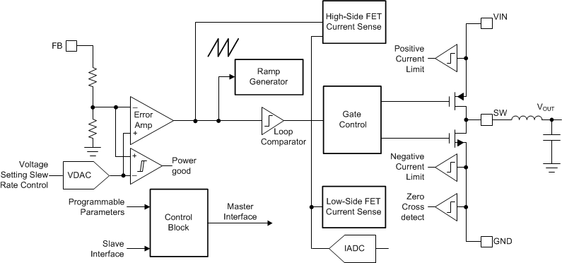
A block diagram of a single core is shown in Figure 6.
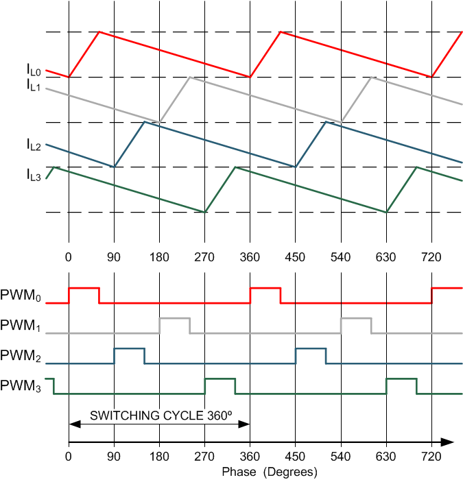
Interleaving switching action of the converters is illustrated in Figure 7. The LP8758-E0 regulator switches each core 90° apart, reducing input ripple current.
 Figure 6. Detailed Block Diagram Showing One Core
  Figure 7. PWM Timings and Inductor Current Waveforms (1)
1. Graph is not in scale and is for illustrative purposes only.