ZHCSLM9B August   2020  – May 2024 LP8866S-Q1

PRODUCTION DATA  

  1.   1
  2. 特性
  3. 应用
  4. 说明
  5. Pin Configuration and Functions
  6. Specifications
    1. 5.1 Absolute Maximum Ratings
    2. 5.2 ESD Ratings
    3. 5.3 Recommended Operating Conditions
    4. 5.4 Thermal Information
    5. 5.5 Electrical Characteristics
    6. 5.6 Logic Interface Characteristics
    7. 5.7 Timing Requirements for I2C Interface
    8.     14
    9. 5.8 Typical Characteristics
  7. Detailed Description
    1. 6.1 Overview
    2. 6.2 Functional Block Diagram
    3. 6.3 Feature Description
      1. 6.3.1 Control Interface
      2. 6.3.2 Function Setting
      3. 6.3.3 Device Supply (VDD)
      4. 6.3.4 Enable (EN)
      5. 6.3.5 Charge Pump
      6. 6.3.6 Boost Controller
        1. 6.3.6.1 Boost Cycle-by-Cycle Current Limit
        2. 6.3.6.2 Controller Min On/Off Time
        3. 6.3.6.3 Boost Adaptive Voltage Control
          1. 6.3.6.3.1 FB Divider Using Two-Resistor Method
          2. 6.3.6.3.2 FB Divider Using Three-Resistor Method
          3. 6.3.6.3.3 FB Divider Using External Compensation
        4. 6.3.6.4 Boost Sync and Spread Spectrum
        5. 6.3.6.5 Boost Output Discharge
        6. 6.3.6.6 Light Load Mode
      7. 6.3.7 LED Current Sinks
        1. 6.3.7.1 LED Output Current Setting
        2. 6.3.7.2 LED Output String Configuration
        3. 6.3.7.3 LED Output PWM Clock Generation
      8. 6.3.8 Brightness Control
        1. 6.3.8.1 Brightness Control Signal Path
        2. 6.3.8.2 Dimming Mode
        3. 6.3.8.3 LED Dimming Frequency
        4. 6.3.8.4 Phase-Shift PWM Mode
        5. 6.3.8.5 Hybrid Mode
        6. 6.3.8.6 Direct PWM Mode
        7. 6.3.8.7 Sloper
        8. 6.3.8.8 PWM Detector Hysteresis
        9. 6.3.8.9 Dither
      9. 6.3.9 Protection and Fault Detections
        1. 6.3.9.1 Supply Faults
          1. 6.3.9.1.1 VIN Undervoltage Faults (VINUVLO)
          2. 6.3.9.1.2 VIN Overvoltage Faults (VINOVP)
          3. 6.3.9.1.3 VDD Undervoltage Faults (VDDUVLO)
          4. 6.3.9.1.4 VIN OCP Faults (VINOCP)
            1. 6.3.9.1.4.1 VIN OCP Current Limit vs. Boost Cycle-by-Cycle Current Limit
          5. 6.3.9.1.5 Charge Pump Faults (CPCAP, CP)
          6. 6.3.9.1.6 CRC Error Faults (CRCERR)
        2. 6.3.9.2 Boost Faults
          1. 6.3.9.2.1 Boost Overvoltage Faults (BSTOVPL, BSTOVPH)
          2. 6.3.9.2.2 Boost Overcurrent Faults (BSTOCP)
          3. 6.3.9.2.3 LEDSET Resistor Missing Faults (LEDSET)
          4. 6.3.9.2.4 MODE Resistor Missing Faults (MODESEL)
          5. 6.3.9.2.5 FSET Resistor Missing Faults (FSET)
          6. 6.3.9.2.6 ISET Resistor Out of Range Faults (ISET)
          7. 6.3.9.2.7 Thermal Shutdown Faults (TSD)
        3. 6.3.9.3 LED Faults
          1. 6.3.9.3.1 Open LED Faults (OPEN_LED)
          2. 6.3.9.3.2 Short LED Faults (SHORT_LED)
          3. 6.3.9.3.3 LED Short to GND Faults (GND_LED)
          4. 6.3.9.3.4 Invalid LED String Faults (INVSTRING)
          5. 6.3.9.3.5 I2C Timeout Faults
        4. 6.3.9.4 Overview of the Fault and Protection Schemes
    4. 6.4 Device Functional Modes
      1. 6.4.1  State Diagram
      2. 6.4.2  Shutdown
      3. 6.4.3  Device Initialization
      4. 6.4.4  Standby Mode
      5. 6.4.5  Power-line FET Soft Start
      6. 6.4.6  Boost Start-Up
      7. 6.4.7  Normal Mode
      8. 6.4.8  Fault Recovery
      9. 6.4.9  Latch Fault
      10. 6.4.10 Start-Up Sequence
    5. 6.5 Programming
      1. 6.5.1 I2C-Compatible Interface
      2. 6.5.2 Programming Examples
        1. 6.5.2.1 General Configuration Registers
        2. 6.5.2.2 Clearing Fault Interrupts
        3. 6.5.2.3 Disabling Fault Interrupts
        4. 6.5.2.4 Diagnostic Registers
  8. Application and Implementation
    1. 7.1 Application Information
    2. 7.2 Typical Applications
      1. 7.2.1 Full Feature Application for Display Backlight
        1. 7.2.1.1 Design Requirements
        2. 7.2.1.2 Detailed Design Procedure
          1. 7.2.1.2.1  Inductor Selection
          2. 7.2.1.2.2  Output Capacitor Selection
          3. 7.2.1.2.3  Input Capacitor Selection
          4. 7.2.1.2.4  Charge Pump Output Capacitor
          5. 7.2.1.2.5  Charge Pump Flying Capacitor
          6. 7.2.1.2.6  Output Diode
          7. 7.2.1.2.7  Switching FET
          8. 7.2.1.2.8  Boost Sense Resistor
          9. 7.2.1.2.9  Power-Line FET
          10. 7.2.1.2.10 Input Current Sense Resistor
          11. 7.2.1.2.11 Feedback Resistor Divider
          12. 7.2.1.2.12 Critical Components for Design
        3. 7.2.1.3 Application Curves
      2. 7.2.2 Application with Basic/Minimal Operation
        1. 7.2.2.1 Design Requirements
        2. 7.2.2.2 Detailed Design Procedure
        3. 7.2.2.3 Application Curves
      3. 7.2.3 SEPIC Mode Application
        1. 7.2.3.1 Design Requirements
        2. 7.2.3.2 Detailed Design Procedure
          1. 7.2.3.2.1  Inductor Selection
          2. 7.2.3.2.2  Coupling Capacitor Selection
          3. 7.2.3.2.3  Output Capacitor Selection
          4. 7.2.3.2.4  Input Capacitor Selection
          5. 7.2.3.2.5  Charge Pump Output Capacitor
          6. 7.2.3.2.6  Charge Pump Flying Capacitor
          7. 7.2.3.2.7  Switching FET
          8. 7.2.3.2.8  Output Diode
          9. 7.2.3.2.9  Switching Sense Resistor
          10. 7.2.3.2.10 Power-Line FET
          11. 7.2.3.2.11 Input Current Sense Resistor
          12. 7.2.3.2.12 Feedback Resistor Divider
          13. 7.2.3.2.13 Critical Components for Design
        3. 7.2.3.3 Application Curves
    3. 7.3 Power Supply Recommendations
    4. 7.4 Layout
      1. 7.4.1 Layout Guidelines
      2. 7.4.2 Layout Example
  9. Device and Documentation Support
    1. 8.1 Device Support
      1. 8.1.1 第三方米6体育平台手机版_好二三四免责声明
    2. 8.2 接收文档更新通知
    3. 8.3 支持资源
    4. 8.4 Trademarks
    5. 8.5 静电放电警告
    6. 8.6 术语表
  10. Revision History
  11. 10Mechanical, Packaging, and Orderable Information

封装选项

机械数据 (封装 | 引脚)
散热焊盘机械数据 (封装 | 引脚)
订购信息

说明

LP8866S-Q1 是一款具有升压控制器的汽车级高效 LED 驱动器。个高精度电流阱支持根据使用的通道数自动调整相移。可通过 I²C 接口或 PWM 输入对 LED 亮度进行全局控制。

升压控制器基于 LED 电流阱余量电压进行自适应输出电压控制。该特性可在所有条件下将升压电压调节到能够满足需要的最低水平,从而更大限度降低功耗。凭借宽范围可调频率,LP8866S-Q1 可避免 AM 无线电频段的干扰。

LP8866S-Q1 支持内置混合 PWM 调光和模拟电流调光,可降低 EMI、延长 LED 使用寿命并提高总光学效率。

器件信息
器件型号(1) 封装 本体尺寸(标称值)
LP8866S-Q1 HTSSOP (38) 9.70mm × 4.40mm
QFN (32) 5mm × 5mm
如需了解所有可用封装,请参阅数据表末尾的可订购米6体育平台手机版_好二三四附录。
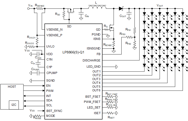
LP8866S-Q1 简化版原理图简化版原理图
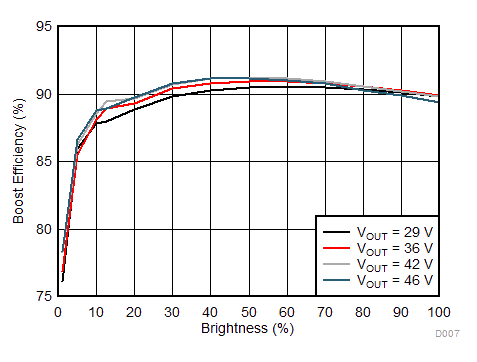
LP8866S-Q1 系统效率系统效率