ZHCSEV2C January 2016 – September 2016 MUX508 , MUX509
PRODUCTION DATA.
8 Parameter Measurement Information
8.1 Truth Tables
Table 2 and Table 3 show the truth tables for the MUX508 and MUX509, respectively.
8.2 On-Resistance
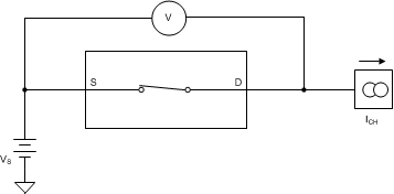
The on-resistance of the MUX50x is the ohmic resistance across the source (Sx, SxA, or SxB) and drain (D, DA, or DB) pins of the device. The on-resistance varies with input voltage and supply voltage. The symbol RON is used to denote on-resistance. The measurement setup used to measure RON is shown in Figure 26. Voltage (V) and current (ICH) are measured using this setup, and RON is computed as shown in Equation 1.
8.3 Off-Leakage Current
There are two types of leakage currents associated with a switch during the off state:
- Source off-leakage current
- Drain off-leakage current
Source off-leakage current is defined as the leakage current flowing into or out of the source pin when the switch is off. This current is denoted by the symbol IS(OFF).
Drain off-leakage current is defined as the leakage current flowing into or out of the drain pin when the switch is off. This current is denoted by the symbol ID(OFF).
The setup used to measure both types of off-leakage currents is shown in Figure 27.
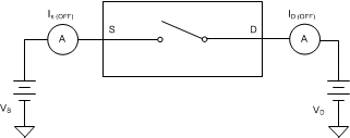 Figure 27. Off-Leakage Measurement Setup
8.4 On-Leakage Current
On-leakage current is defined as the leakage current that flows into or out of the drain pin when the switch is in the on state. The source pin is left floating during the measurement. Figure 28 shows the circuit used for measuring the on-leakage current, denoted by ID(ON).
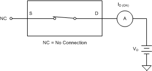 Figure 28. On-Leakage Measurement Setup
8.5 Transition Time
Transition time is defined as the time taken by the output of the MUX50x to rise or fall to 90% of the transition after the digital address signal has fallen or risen to the 50% of the transition. Figure 29 shows the setup used to measure transition time, denoted by the symbol tt.
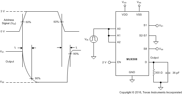 Figure 29. Transition-Time Measurement Setup
8.6 Break-Before-Make Delay
Break-before-make delay is a safety feature that prevents two inputs from connecting when the MUX50x is switching. The MUX50x output first breaks from the on-state switch before making the connection with the next on-state switch. The time delay between the break and the make is known as a break-before-make delay. Figure 30 shows the setup used to measure break-before-make delay, denoted by the symbol tBBM.
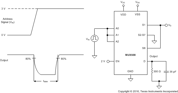 Figure 30. Break-Before-Make Delay Measurement Setup
8.7 Turn-On and Turn-Off Time
Turn-on time is defined as the time taken by the output of the MUX50x to rise to a 90% final value after the enable signal has risen to a 50% final value. Figure 31 shows the setup used to measure turn-on time. Turn-on time is denoted by the symbol tON.
Turn-off time is defined as the time taken by the output of the MUX50x to fall to a 10% initial value after the enable signal has fallen to a 50% initial value. Figure 31 shows the setup used to measure turn-off time. Turn-off time is denoted by the symbol tOFF.
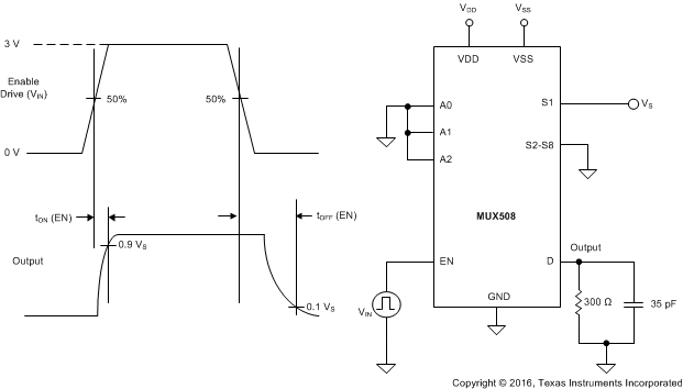 Figure 31. Turn-On and Turn-Off Time Measurement Setup
8.8 Charge Injection
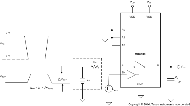
The MUX50x have a simple transmission-gate topology. Any mismatch in capacitance between the NMOS and PMOS transistors results in a charge injected into the drain or source during the falling or rising edge of the gate signal. The amount of charge injected into the source or drain of the device is known as charge injection, and is denoted by the symbol QINJ. Figure 32 shows the setup used to measure charge injection.
8.9 Off Isolation
Off isolation is defined as the voltage at the drain pin (D, DA, or DB) of the MUX50x when a 1-VRMS signal is applied to the source pin (Sx, SxA, or SxB) of an off-channel. Figure 33 shows the setup used to measure off isolation. Use Equation 2 to compute off isolation.
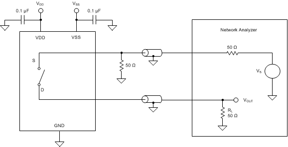 Figure 33. Off Isolation Measurement Setup

8.10 Channel-to-Channel Crosstalk
Channel-to-channel crosstalk is defined as the voltage at the source pin (Sx, SxA, or SxB) of an off-channel, when a 1-VRMS signal is applied at the source pin of an on-channel. Figure 34 shows the setup used to measure, and Equation 3 is the equation used to compute, channel-to-channel crosstalk.
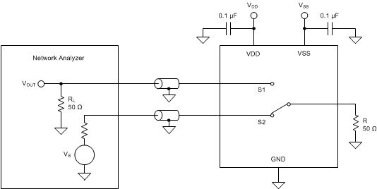 Figure 34. Channel-to-Channel Crosstalk Measurement Setup

8.11 Bandwidth
Bandwidth is defined as the range of frequencies that are attenuated by < 3 dB when the input is applied to the source pin of an on-channel and the output is measured at the drain pin of the MUX50x. Figure 35 shows the setup used to measure bandwidth of the mux. Use Equation 4 to compute the attenuation.
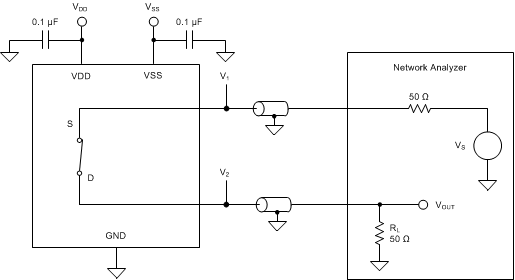 Figure 35. Bandwidth Measurement Setup

8.12 THD + Noise
The total harmonic distortion (THD) of a signal is defined as the ratio of the sum of the powers of all harmonic components to the power of the fundamental frequency at the mux output. The on-resistance of the MUX50x varies with the amplitude of the input signal and results in distortion when the drain pin is connected to a low-impedance load. Total harmonic distortion plus noise is denoted as THD+N. Figure 36 shows the setup used to measure the THD+N of the MUX50x.
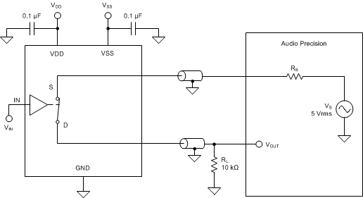 Figure 36. THD+N Measurement Setup
