ZHCS399E August 2011 – January 2017 OMAP-L132
PRODUCTION DATA.
- 1器件概述
- 2Revision History
-
3Device Comparison
- 3.1 Device Characteristics
- 3.2 Device Compatibility
- 3.3 ARM Subsystem
- 3.4 DSP Subsystem
- 3.5 Memory Map Summary
- 3.6 Pin Assignments
- 3.7 Pin Multiplexing Control
- 3.8
Terminal Functions
- 3.8.1 Device Reset, NMI and JTAG
- 3.8.2 High-Frequency Oscillator and PLL
- 3.8.3 Real-Time Clock and 32-kHz Oscillator
- 3.8.4 DEEPSLEEP Power Control
- 3.8.5 External Memory Interface A (EMIFA)
- 3.8.6 DDR2/mDDR Controller
- 3.8.7 Serial Peripheral Interface Modules (SPI)
- 3.8.8 Programmable Real-Time Unit (PRU)
- 3.8.9 Enhanced Capture/Auxiliary PWM Modules (eCAP0)
- 3.8.10 Enhanced Pulse Width Modulators (eHRPWM)
- 3.8.11 Boot
- 3.8.12 Universal Asynchronous Receiver/Transmitters (UART0, UART1, UART2)
- 3.8.13 Inter-Integrated Circuit Modules(I2C0, I2C1)
- 3.8.14 Timers
- 3.8.15 Multichannel Audio Serial Ports (McASP)
- 3.8.16 Multichannel Buffered Serial Ports (McBSP)
- 3.8.17 Universal Serial Bus Modules (USB0)
- 3.8.18 Ethernet Media Access Controller (EMAC)
- 3.8.19 Multimedia Card/Secure Digital (MMC/SD)
- 3.8.20 General Purpose Input Output
- 3.8.21 Reserved and No Connect
- 3.8.22 Supply and Ground
- 3.9 Unused Pin Configurations
- 4Device Configuration
-
5Specifications
- 5.1 Absolute Maximum Ratings Over Operating Junction Temperature Range (Unless Otherwise Noted)
- 5.2 Handling Ratings
- 5.3 Recommended Operating Conditions
- 5.4 Notes on Recommended Power-On Hours (POH)
- 5.5 Electrical Characteristics Over Recommended Ranges of Supply Voltage and Operating Junction Temperature (Unless Otherwise Noted)
-
6Peripheral Information and Electrical Specifications
- 6.1 Parameter Information
- 6.2 Recommended Clock and Control Signal Transition Behavior
- 6.3 Power Supplies
- 6.4 Reset
- 6.5 Crystal Oscillator or External Clock Input
- 6.6 Clock PLLs
- 6.7 Interrupts
- 6.8 Power and Sleep Controller (PSC)
- 6.9 Enhanced Direct Memory Access Controller (EDMA3)
- 6.10 External Memory Interface A (EMIFA)
- 6.11
DDR2/mDDR Memory Controller
- 6.11.1 DDR2/mDDR Memory Controller Electrical Data/Timing
- 6.11.2 DDR2/mDDR Memory Controller Register Description(s)
- 6.11.3
DDR2/mDDR Interface
- 6.11.3.1 DDR2/mDDR Interface Schematic
- 6.11.3.2 Compatible JEDEC DDR2/mDDR Devices
- 6.11.3.3 PCB Stackup
- 6.11.3.4 Placement
- 6.11.3.5 DDR2/mDDR Keep Out Region
- 6.11.3.6 Bulk Bypass Capacitors
- 6.11.3.7 High-Speed Bypass Capacitors
- 6.11.3.8 Net Classes
- 6.11.3.9 DDR2/mDDR Signal Termination
- 6.11.3.10 VREF Routing
- 6.11.3.11 DDR2/mDDR CK and ADDR_CTRL Routing
- 6.11.3.12 DDR2/mDDR Boundary Scan Limitations
- 6.12 Memory Protection Units
- 6.13 MMC / SD / SDIO (MMCSD0, MMCSD1)
- 6.14 Multichannel Audio Serial Port (McASP)
- 6.15
Multichannel Buffered Serial Port (McBSP)
- 6.15.1 McBSP Peripheral Register Description(s)
- 6.15.2
McBSP Electrical Data/Timing
- 6.15.2.1
Multichannel Buffered Serial Port (McBSP) Timing
- Table 6-52 Timing Requirements for McBSP0 [1.2V, 1.1V] (see )
- Table 6-53 Timing Requirements for McBSP0 [1.0V] (see )
- Table 6-54 Switching Characteristics for McBSP0 [1.2V, 1.1V] (see )
- Table 6-55 Switching Characteristics for McBSP0 [1.0V] (see )
- Table 6-56 Timing Requirements for McBSP1 [1.2V, 1.1V] (see )
- Table 6-57 Timing Requirements for McBSP1 [1.0V] (see )
- Table 6-58 Switching Characteristics for McBSP1 [1.2V, 1.1V] (see )
- Table 6-59 Switching Characteristics for McBSP1 [1.0V] (see )
- Table 6-60 Timing Requirements for McBSP0 FSR When GSYNC = 1 (see )
- Table 6-61 Timing Requirements for McBSP1 FSR When GSYNC = 1 (see )
- 6.15.2.1
Multichannel Buffered Serial Port (McBSP) Timing
- 6.16
Serial Peripheral Interface Ports (SPI0, SPI1)
- 6.16.1 SPI Peripheral Registers Description(s)
- 6.16.2
SPI Electrical Data/Timing
- 6.16.2.1
Serial Peripheral Interface (SPI) Timing
- Table 6-63 General Timing Requirements for SPI0 Master Modes
- Table 6-64 General Timing Requirements for SPI0 Slave Modes
- Table 6-71 General Timing Requirements for SPI1 Master Modes
- Table 6-72 General Timing Requirements for SPI1 Slave Modes
- Table 6-73 Additional SPI1 Master Timings, 4-Pin Enable Option
- Table 6-74 Additional SPI1 Master Timings, 4-Pin Chip Select Option
- 6.16.2.1
Serial Peripheral Interface (SPI) Timing
- 6.17 Inter-Integrated Circuit Serial Ports (I2C)
- 6.18 Universal Asynchronous Receiver/Transmitter (UART)
- 6.19 Universal Serial Bus OTG Controller (USB0) [USB2.0 OTG]
- 6.20 Ethernet Media Access Controller (EMAC)
- 6.21 Management Data Input/Output (MDIO)
- 6.22 Enhanced Capture (eCAP) Peripheral
- 6.23 Enhanced High-Resolution Pulse-Width Modulator (eHRPWM)
- 6.24 Timers
- 6.25 Real Time Clock (RTC)
- 6.26 General-Purpose Input/Output (GPIO)
- 6.27 Programmable Real-Time Unit Subsystem (PRUSS)
- 6.28 Emulation Logic
- 7Device and Documentation Support
- 8Mechanical Packaging and Orderable Information
6.6.1 PLL Device-Specific Information
The device DSP generates the high-frequency internal clocks it requires through an on-chip PLL.
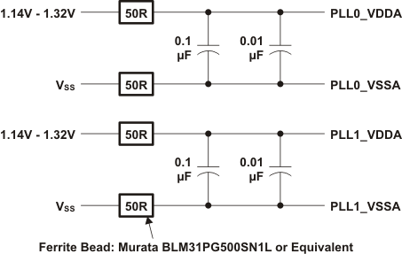
The PLL requires some external filtering components to reduce power supply noise as shown in Figure 6-8.
 Figure 6-8 PLL External Filtering Components
The external filtering components shown above provide noise immunity for the PLLs. PLL0_VDDA and PLL1_VDDA should not be connected together to provide noise immunity between the two PLLs. Likewise, PLL0_VSSA and PLL1_VSSA should not be connected together.
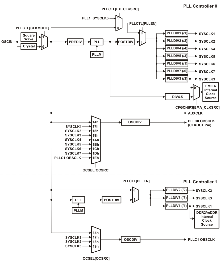
The input to the PLL is either from the on-chip oscillator or from an external clock on the OSCIN pin. PLL0 outputs seven clocks that have programmable divider options. PLL1 outputs three clocks that have programmable divider options. Figure 6-9 illustrates the high-level view of the PLL Topology.
The PLLs are disabled by default after a device reset. They must be configured by software according to the allowable operating conditions listed in Table 6-4 before enabling the device to run from the PLL by setting PLLEN = 1.
 Figure 6-9 PLL Topology
Table 6-4 Allowed PLL Operating Conditions (PLL0 and PLL1)
| NO. | PARAMETER | Default
Value |
MIN | MAX | UNIT |
|---|---|---|---|---|---|
| 1 | PLLRST: Assertion time during initialization | N/A | 1000 | N/A | ns |
| 2 | Lock time: The time that the application has to wait for the PLL to acquire lock before setting PLLEN, after changing PREDIV, PLLM, or OSCIN | N/A | N/A |  (1) (1)
|
OSCIN
cycles |
| 3 | PREDIV: Pre-divider value | /1 | /1 | /32 | - |
| 4 | PLLREF: PLL input frequency | 12 | 30 (if internal oscillator is used)
50 (if external clock is used) |
MHz | |
| 5 | PLLM: PLL multiplier values | x20 | x4 | x32 | |
| 6 | PLLOUT: PLL output frequency | N/A | 200 | 600 | MHz |
| 7 | POSTDIV: Post-divider value | /1 | /1 | /32 | - |