ZHCSWB3A September 2000 – June 2024 OPA2241 , OPA2251 , OPA241 , OPA251 , OPA4241 , OPA4251
PRODUCTION DATA
- 1
- 1特性
- 2应用
- 3说明
- 4Pin Configuration and Functions
-
5Specifications
- 5.1 Absolute Maximum Ratings
- 5.2 Recommended Operating Conditions
- 5.3 Thermal Information for OPA241 and OPA251
- 5.4 Thermal Information for OPA2241 and OPA2251
- 5.5 Thermal Information for OPA4241 and OPA4251
- 5.6 Electrical Characteristics for VS = 2.7V to 5V
- 5.7 Electrical Characteristics for VS = ±15V
- 5.8 Typical Characteristics
- 6Application and Implementation
- 7Device and Documentation Support
- 8Revision History
- 9Mechanical, Packaging, and Orderable Information
6.1.2 Offset Voltage Trim
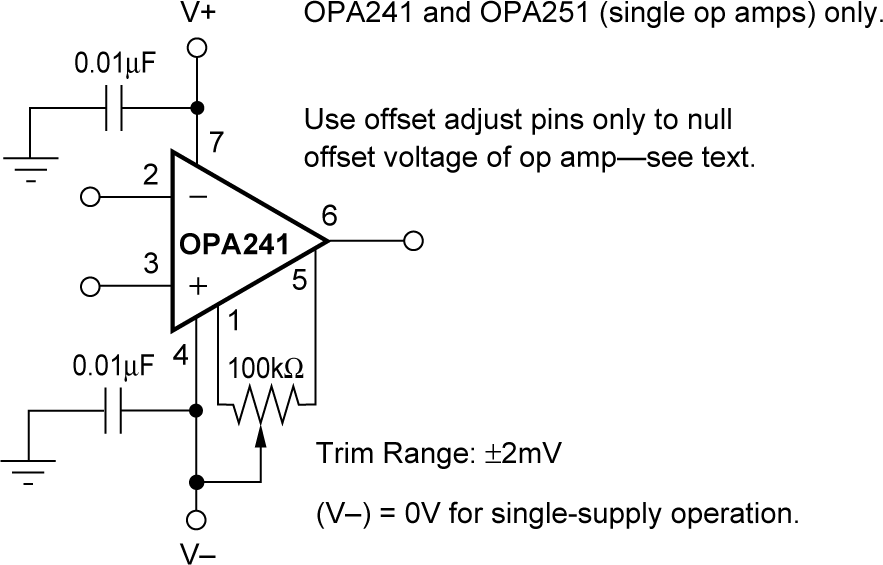
As previously mentioned, the OPAx241 series offset voltage is laser-trimmed at 5V. The OPAx251 series is trimmed at ±15V. The initial offset is so low that user adjustment is usually not required. However, the OPA241 and OPA251 (single op-amp versions) provide offset voltage trim connections on pins 1 and 5. Figure 6-1shows how the offset voltage can be adjusted by connecting a potentiometer. Only use this adjustment to null the offset of the op amp, not to adjust system offset or offset produced by the signal source. Nulling offset can degrade the offset drift behavior of the op amp. While predicting the exact change in drift is not possible, the effect is usually small.
 Figure 6-1 OPA241 and OPA251 Offset Voltage Trim Circuit