ZHCSJY2A June 2019 – September 2019 OPA2834
PRODUCTION DATA.
- 1 特性
- 2 应用
- 3 说明
- 4 修订历史记录
- 5 Device Comparison Table
- 6 Pin Configuration and Functions
- 7 Specifications
- 8 Detailed Description
- 9 Application and Implementation
- 10Power Supply Recommendations
- 11Layout
- 12器件和文档支持
- 13机械、封装和可订购信息
9.2.4 Microphone Pre-Amplifier
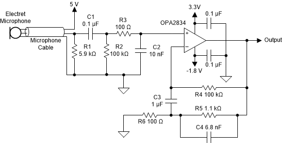
 Figure 60. Low-Power Microphone Pre-Amplifier
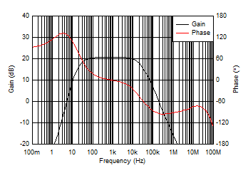
 Figure 60 shows an example circuit of the audio pre-amplifier application using OPA2834. The excellent distortion performance and the ultra-low quiescent current, make OPA2834 a very attractive solution for the portable and handheld audio instruments. Figure 60 circuit is a bandpass filter with frequency cutoff at 5 Hz and 180 kHz. The OPA2834 is connected to a positive 3.3 V and a negative 1.8 V supply. the primary reason for the skew in the power supply is to enable the maximum dynamic range possible to the user. The VICR of OPA2834 mentioned in Electrical Characteristics: 3V to 5V is 1.1 V from the positive rail. Thus having a skewed power supply like in Figure 60 gives a common-mode input range from -2 V up to 2.2 V.
 Figure 61. Frequency Response of Microphone Pre-Amplifier