ZHCS228A June   2011  – February 2024 OPA564-Q1

PRODUCTION DATA  

  1.   1
  2. 特性
  3. 应用
  4. 说明
  5. Device Comparison Table
  6. Pin Configuration and Functions
  7. Specifications
    1. 6.1 Absolute Maximum Ratings
    2. 6.2 ESD Ratings
    3. 6.3 Recommended Operating Conditions
    4. 6.4 Thermal Information
    5. 6.5 Electrical Characteristics
    6. 6.6 Typical Characteristics
  8. Detailed Description
    1. 7.1 Overview
    2. 7.2 Functional Block Diagram
    3. 7.3 Feature Description
      1. 7.3.1 Adjustable Current Limit
        1. 7.3.1.1 Setting the Current Limit
      2. 7.3.2 Enable and Shutdown (E/S) Pin
      3. 7.3.3 Input Protection
      4. 7.3.4 Output Shutdown
      5. 7.3.5 Microcontroller Compatibility
      6. 7.3.6 Current Limit Flag
      7. 7.3.7 Thermal Protection
      8. 7.3.8 Junction Temperature Measurement Using TSENSE
    4. 7.4 Device Functional Modes
  9. Application and Implementation
    1. 8.1 Application Information
      1. 8.1.1 Basic Configuration
      2. 8.1.2 Output-Stage Compensation
      3. 8.1.3 Output Protection
      4. 8.1.4 Power Dissipation and Safe Operating Area
    2. 8.2 Typical Applications
      1. 8.2.1 Improved Howland Current Pump
      2. 8.2.2 Programmable Power Supply
      3. 8.2.3 Powerline Communication
      4. 8.2.4 Motor-Drive Circuit
      5. 8.2.5 DC Motor-Speed Controller (Without Tachometer)
      6. 8.2.6 Generating VDIG
      7. 8.2.7 Temperature Measurement
    3. 8.3 Power Supply Recommendations
    4. 8.4 Layout
      1. 8.4.1 Layout Guidelines
        1. 8.4.1.1 Thermally Enhanced PowerPAD™ Integrated Circuit Package
          1. 8.4.1.1.1 Bottom-Side Thermal Pad Assembly Process
  10. Device and Documentation Support
    1. 9.1 接收文档更新通知
    2. 9.2 支持资源
    3. 9.3 Trademarks
    4. 9.4 静电放电警告
    5. 9.5 术语表
  11. 10Revision History
  12. 11Mechanical, Packaging, and Orderable Information

封装选项

机械数据 (封装 | 引脚)
散热焊盘机械数据 (封装 | 引脚)
订购信息

DC Motor-Speed Controller (Without Tachometer)

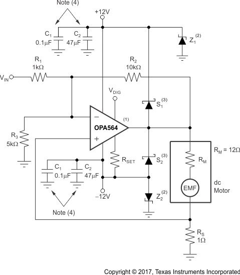
For applications where good control of the speed of the motor is desired, but the precision of a tachometer control is not required, the circuit in Figure 8-11 provides control by using feedback of the current consumption to adjust the motor drive.
GUID-06E95779-96DE-4A92-9EC4-CF32A8F01DC9-low.gif
1. IFLAG and TFLAG connections are not shown.
2. Z1, Z2 = zener diodes (IN5246 or equivalent). Select Z1 and Z2 diodes that are capable of the maximum anticipated surge current.
3. S1, S2 = Schottky diodes (STPS1L40 or equivalent).
4. C1 = high-frequency bypass capacitors; C2 = low-frequency bypass capacitors (minimum of 10μF for every 1A peak current).
Figure 8-11 DC Motor-Speed Controller (Without Tachometer)

For more information on this circuit, see the DC Motor Speed Controller: Control a DC Motor without Tachometer Feedback the application bulletin, available for download at www.ti.com.