at VS+ = 12 V, VS– = –12 V,
RL = 1 kΩ, input and output are biased to midsupply, and
TA ≈ 25°C. For AC specifications, VO = 2 VPP, G
= 2 V/V, RF = 1 kΩ, and CL = 4.7 pF (unless otherwise
noted)
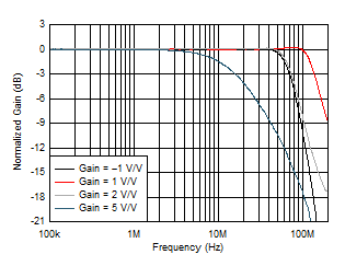 Figure 6-18 Noninverting Small-Signal Frequency Response vs Gain
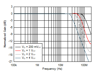 Figure 6-20 Large-Signal Frequency Response vs Output Voltage
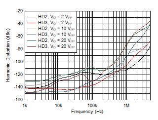 Figure 6-22 Harmonic Distortion vs Frequency vs Vo
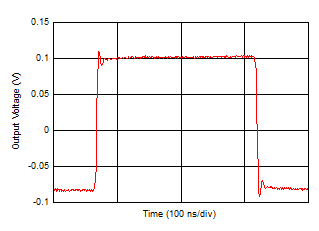
| See Figure 8-1, gain = 1 V/V, RF = 0 Ω, CL =
10 pF |
Figure 6-24 Small-Signal Transient Response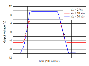 Figure 6-26 Large-Signal Transient Response
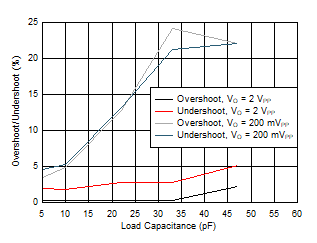 Figure 6-28 Overshoot and Undershoot vs CL
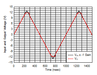 Figure 6-30 Output Overdrive Recovery
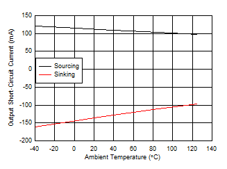
| Output saturated and then
short-circuited |
Figure 6-32 Output Short-Circuit Current vs Ambient Temperature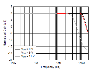
| See Figure 8-1, VO = 20 mVPP, gain = 1 V/V,
CL = 4.7 pF, |
| RF = 0 Ω |
Figure 6-19 Small-Signal Frequency Response vs Output Common-Mode Voltage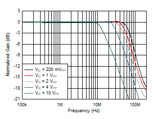 Figure 6-21 Large-Signal Frequency Response vs Vo
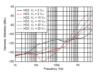 Figure 6-23 Harmonic Distortion vs Frequency vs Vo
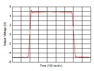 Figure 6-25 Large-Signal Transient Response
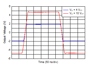 Figure 6-27 Large-Signal Transient Response
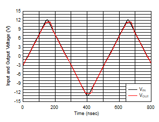 Figure 6-29 Input
Overdrive Recovery
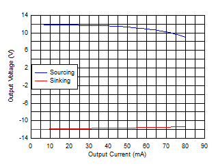 Figure 6-31 Output Voltage Range vs Load Current
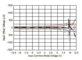 Figure 6-33 Input
Offset Voltage vs Input Common-Mode Voltage


