ZHCSMO3J june 2020 – june 2023 OPA2863 , OPA4863 , OPA863
PRODUCTION DATA
- 1
- 1 特性
- 2 应用
- 3 说明
- 4 Revision History
- 5 Device Comparison Table
- 6 Pin Configuration and Functions
-
7 Specifications
- 7.1 Absolute Maximum Ratings
- 7.2 ESD Ratings
- 7.3 Recommended Operating Conditions
- 7.4 Thermal Information: OPA863
- 7.5 Thermal Information: OPA2863
- 7.6 Thermal Information: OPA4863
- 7.7 Electrical Characteristics: VS = 10 V
- 7.8 Electrical Characteristics: VS = 3 V
- 7.9 Typical Characteristics: VS = 10 V
- 7.10 Typical Characteristics: VS = 3 V
- 7.11 Typical Characteristics: VS = 3 V to 10 V
- 8 Detailed Description
- 9 Application and Implementation
- 10Device and Documentation Support
- 11Mechanical, Packaging, and Orderable Information
8.4.1 Power-Down Mode
The OPAx863 includes a power-down mode for low-power standby operation with a quiescent current of only 1.5 μA (maximum) with a 3-V supply and high output impedance. Many low-power systems are active for only a small time interval when the parameters of interest are measured and remain in low-power standby mode for a majority of the time and an overall small average power consumption. The OPAx863 enables such a low-power operation with quick turn-on within less than 6.5 μs. See the Electrical Characteristics tables for power-down pin control thresholds.
Always drive PD pin to avoid false triggering and oscillations. If power-down mode is not used, then connect the PD pin to VS+. For applications that need power-down mode, use an external pull-up resistor from the PD pin to VS+ (driven with an open-collector power-down control logic).

Figure 8-2 Power Down Control
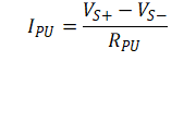
Figure 8-2 shows the choice of value of the pull-up resistor RPU, which impacts the current consumption in power-down mode. Using a large RPU reduces power consumption, but increases the noise at the PD pin, which can cause the amplifier to power down. A 1‑nF capacitor can be used in parallel with RPU to avoid coupling of external noise and false triggering. For the case of the PD pin driven to VS-, the IPU current through RPU is given as:
