SLTS278J November 2010 – March 2020 PTH08T250W
PRODUCTION DATA.
- 1 Features
- 2 Applications
- 3 Description
- 4 Revision History
- 5 Description (continued)
- 6 Pin Configuration and Functions
- 7 Specifications
- 8 Detailed Description
-
9 Application and Implementation
- 9.1
Typical Application
- 9.1.1
Detailed Design Procedure
- 9.1.1.1 Adjusting the Output Voltage
- 9.1.1.2
Capacitor Recommendations for the PTH08T250W Power Module
- 9.1.1.2.1 Capacitor Technologies
- 9.1.1.2.2 Input Capacitor (Required)
- 9.1.1.2.3 Input Capacitor Information
- 9.1.1.2.4 Output Capacitor (Required)
- 9.1.1.2.5 Output Capacitor Information
- 9.1.1.2.6 TurboTrans Output Capacitance
- 9.1.1.2.7 Non-TurboTrans Output Capacitance
- 9.1.1.2.8 Designing for Fast Load Transients
- 9.1.1.2.9 Capacitor Table
- 9.1.1.3 TurboTrans™ Technology
- 9.1.1.4 TurboTrans™ Selection
- 9.1.1.5 Undervoltage Lockout (UVLO)
- 9.1.1.6 On/Off Inhibit
- 9.1.1.7 Current Sharing
- 9.1.1.8 Prebias Startup Capability
- 9.1.1.9 SmartSync Technology
- 9.1.1.10 Auto-Track™ Function
- 9.1.1
Detailed Design Procedure
- 9.1
Typical Application
- 10Device and Documentation Support
- 11Mechanical, Packaging, and Orderable Information
9.1.1.5.1 UVLO Adjustment
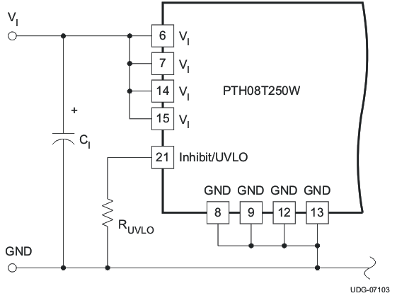
The UVLO feature of the PTH08T250W module allows for limited adjustment of the ON threshold voltage. The adjustment is made via the Inhbit/UVLO Prog control pin (pin 11) using a single resistor (see Figure 19). When pin 11 is left open circuit, the ON threshold voltage is internally set to its default value, which is 4.3 volts. The ON threshold might need to be raised if the module is powered from a tightly regulated 12-V bus. Adjusting the threshold prevents the module from operating if the input bus fails to completely rise to its specified regulation voltage.
Equation 4 determines the value of RUVLO required to adjust VTHD to a new value. The default value is 4.3 V, and it may only be adjusted to a higher value.

Table 7 lists the standard resistor values for RUVLO for different values of the on-threshold (VTHD) voltage.
Table 7. Standard RUVLO Values for Various VTHD Values
| VTHD (V) | 5.5 | 6.0 | 6.5 | 7.0 | 7.5 | 8.0 | 8.5 | 9.0 | 9.5 | 10.0 | 10.5 | 11.0 |
| RUVLO (kΩ) | 255 | 165 | 121 | 95.3 | 78.7 | 68.1 | 59.0 | 52.3 | 46.4 | 42.2 | 39.2 | 35.7 |
 Figure 19. Undervoltage Lockout Adjustment Resistor Placement