ZHCSFI5 September 2016 REF6225 , REF6230 , REF6233 , REF6241 , REF6245 , REF6250
PRODUCTION DATA.
11 Layout
11.1 Layout Guidelines
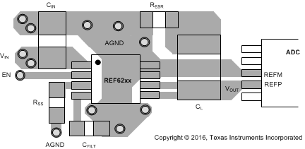
Figure 61 illustrates an example of a PCB layout for a data-acquisition system using the REF62xx. Some key considerations are:
- Connect low-ESR, 0.1-μF ceramic bypass capacitors between the VIN pin and ground.
- Place the REF62xx output capacitor (CL) and the ADC as close to each other as possible.
- Run two separate traces between VOUT_F, VOUT_S and the output capacitor, as shown in Figure 61.
- Short the GND_F and GND_S pins with a solid plane, and extend this plane to connect to the output capacitor CL, as shown in Figure 61.
- Use a solid ground plane to help distribute heat and reduces electromagnetic interference (EMI) noise pickup.
- Place the external components as close to the device as possible. This configuration prevents parasitic errors (such as the Seebeck effect) from occurring.
- Do not run sensitive analog traces in parallel with digital traces. Avoid crossing digital and analog traces if possible, and only make perpendicular crossings when absolutely necessary.
11.2 Layout Example
 Figure 61. Layout Example