ZHCS785I February 2012 – January 2021 SN6501
PRODUCTION DATA
- 1 特性
- 2 应用
- 3 说明
- 4 Pin Configuration and Functions
- 5 Specifications
- 6 Parameter Measurement Information
- 7 Detailed Description
- 8 Application and Implementation
- 9 Power Supply Recommendations
- 10Layout
- 11Device and Documentation Support
- 12Mechanical, Packaging, and Orderable Information
8.2.5 Application Circuits
The following application circuits are shown for a 3.3 V input supply commonly taken from the local, regulated micro-controller supply. For 5 V input voltages requiring different turn ratios refer to the transformer manufacturers and their websites listed in #GUID-04C8C4A5-23A7-429F-BCB7-D04F126623C6/SLLSEA04372.
Table 8-4 Transformer Manufacturers
| Coilcraft Inc. | http://www.coilcraft.com |
| Halo-Electronics Inc. | http://www.haloelectronics.com |
| Murata Power Solutions | http://www.murata-ps.com |
| Wurth Electronics Midcom Inc | http://www.midcom-inc.com |
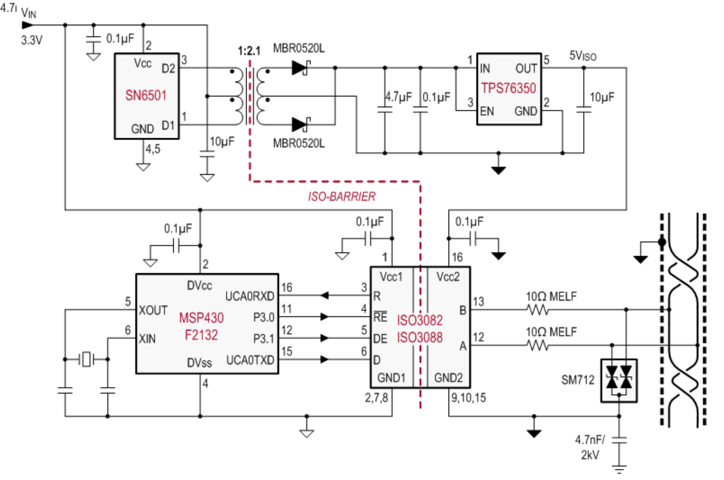 Figure 8-12 Isolated RS-485 Interface
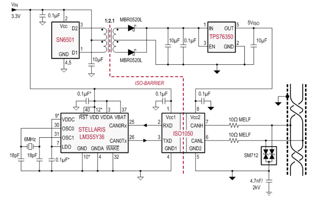 Figure 8-13 Isolated Can Interface
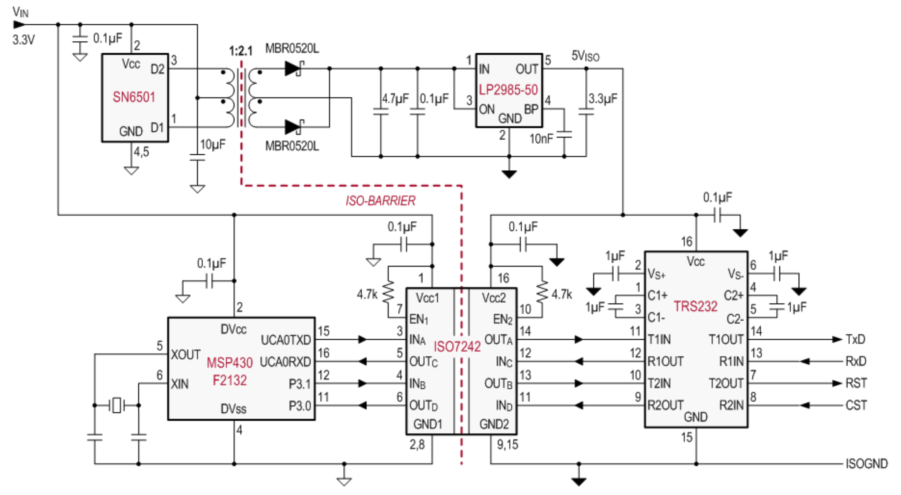 Figure 8-14 Isolated RS-232 Interface
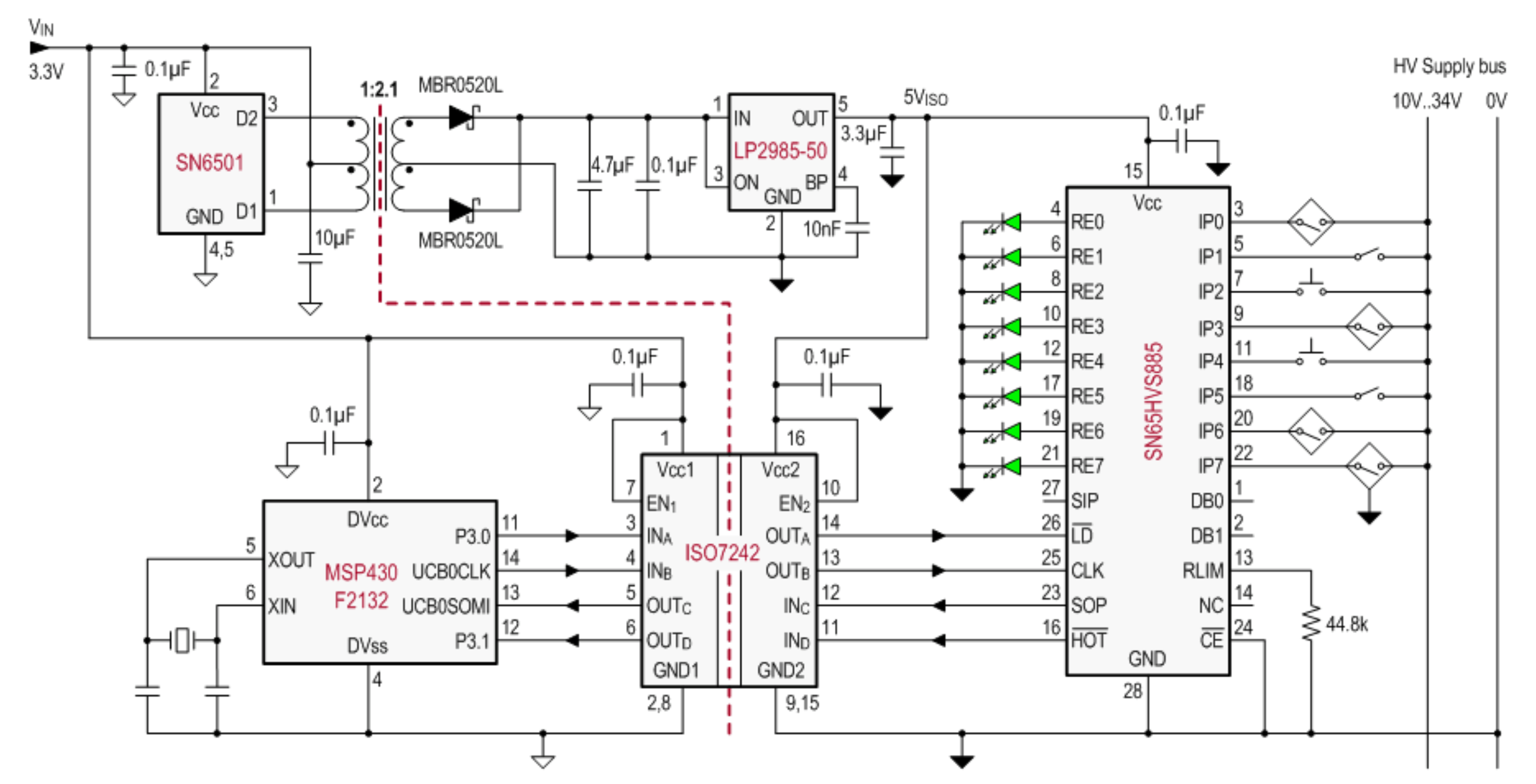 Figure 8-15 Isolated Digital Input Module
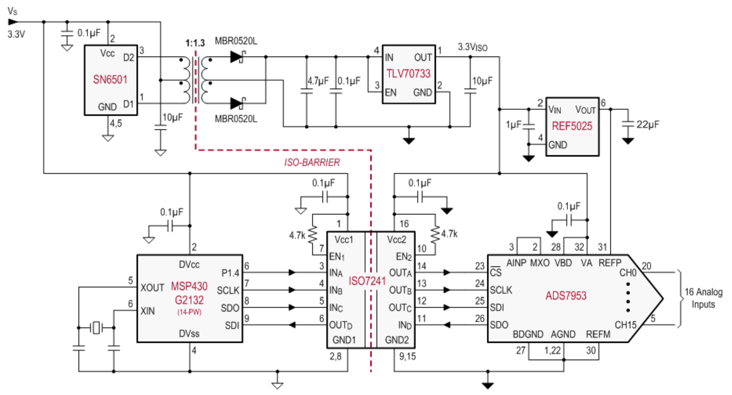 Figure 8-16 Isolated SPI Interface for an Analog Input Module With 16 Inputs
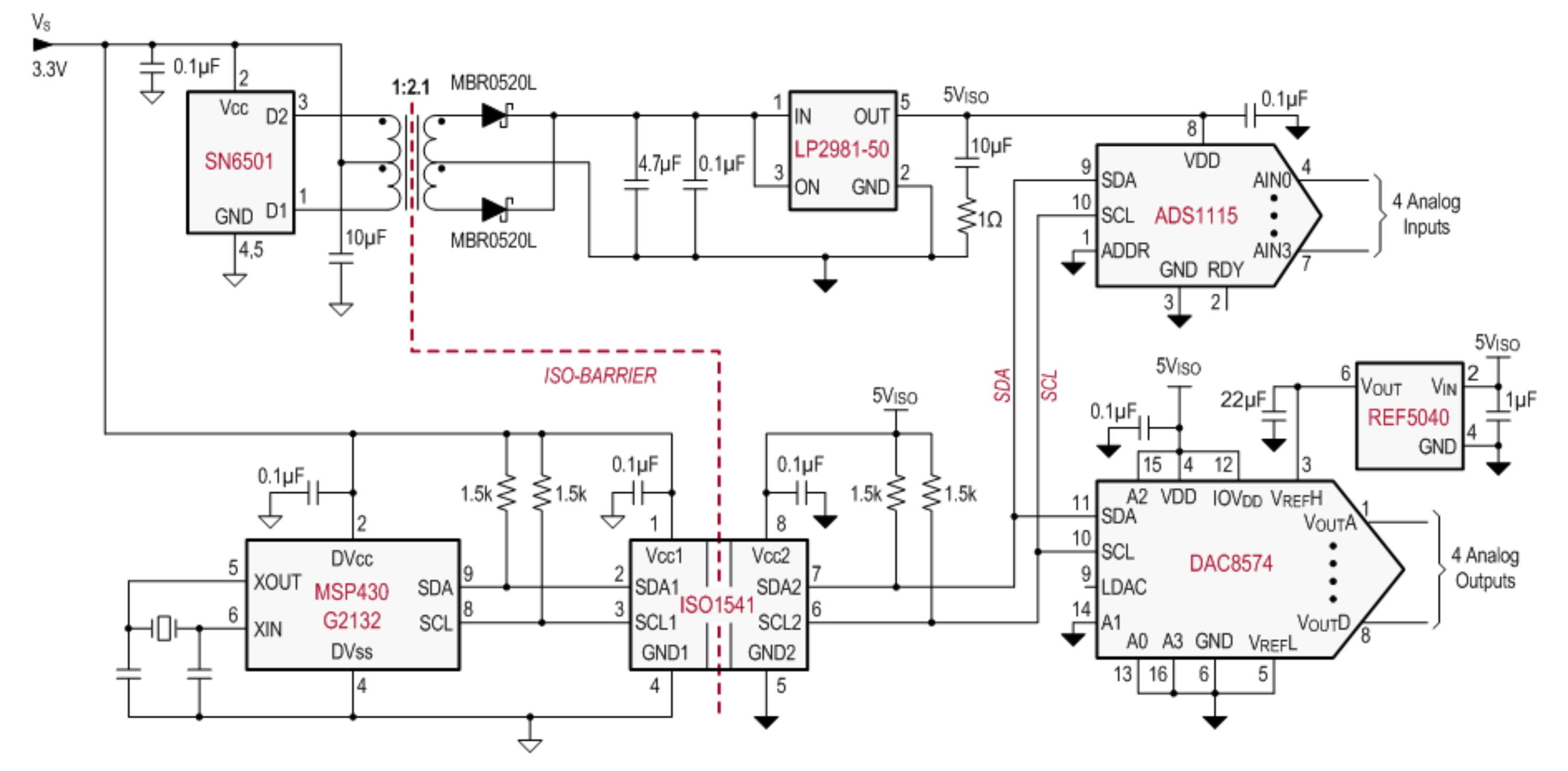 Figure 8-17 Isolated I2C Interface for an Analog Data Acquisition System With 4 Inputs and 4 Outputs
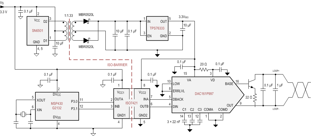 Figure 8-18 Isolated 4-20 mA Current Loop