ZHCS601D
December 2011 – May 2015
SN65HVD255
,
SN65HVD256
,
SN65HVD257
PRODUCTION DATA.
1
特性
2
应用
3
说明
4
修订历史记录
5
Device Options
6
Pin Configuration and Functions
7
Specifications
7.1
Absolute Maximum Ratings
7.2
ESD Ratings
7.3
Recommended Operating Conditions
7.4
Thermal Information
7.5
Electrical Characteristics
7.6
Power Dissipation
7.7
Switching Characteristics
7.8
Typical Characteristics
8
Parameter Measurement Information
9
Detailed Description
9.1
Overview
9.2
Functional Block Diagram
9.3
Feature Description
9.3.1
TXD Dominant Timeout (DTO)
9.3.2
RXD Dominant Timeout (SN65HVD257)
9.3.3
Thermal Shutdown
9.3.4
Undervoltage Lockout
9.3.5
FAULT Pin (SN65HVD257)
9.3.6
Unpowered Device
9.3.7
Floating Pins
9.3.8
CAN Bus Short-Circuit Current Limiting
9.4
Device Functional Modes
9.4.1
Operating Modes
9.4.2
Can Bus States
9.4.3
Normal Mode
9.4.4
Silent Mode
9.4.5
Digital Inputs and Outputs
9.4.5.1
5-V VCC Only Devices (SN65HVD255 and SN65HVD257)
9.4.5.2
5-V VCC With VRXD RXD Output Supply Devices (SN65HVD256)
9.4.5.3
5-V VCC with FAULT Open-Drain Output Device (SN65HVD257)
10
Application and Implementation
10.1
Application Information
10.1.1
Bus Loading, Length, and Number of Nodes
10.2
Typical Applications
10.2.1
Typical 5-V Microcontroller Application
10.2.1.1
Design Requirements
10.2.1.1.1
CAN Termination
10.2.1.2
Detailed Design Procedure
10.2.1.2.1
Example: Functional Safety Using the SN65HVD257 in a Redundant Physical Layer CAN Network Topology
10.2.1.3
Application Curves
10.2.2
Typical 3.3-V Microcontroller Application
11
Power Supply Recommendations
12
Layout
12.1
Layout Guidelines
12.2
Layout Example
13
器件和文档支持
13.1
相关链接
13.2
商标
13.3
静电放电警告
13.4
术语表
14
机械、封装和可订购信息
封装选项
机械数据 (封装 | 引脚)
D|8
MSOI002K
散热焊盘机械数据 (封装 | 引脚)
订购信息
zhcs601d_oa
zhcs601d_pm
8 Parameter Measurement Information
Figure 4. RXD Dominant Timeout Test Circuit and Measurement
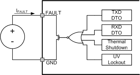
Figure 5. FAULT Test and Measurement
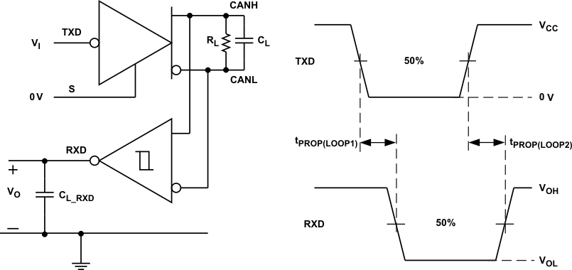
Figure 6. Driver Test Circuit and Measurement
Figure 7. Receiver Test Circuit and Measurement
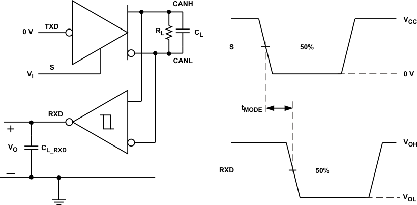
Figure 8. t
MODE
Test Circuit and Measurement
Table 1. Receiver Differential Input Voltage Threshold Test
INPUT
OUTPUT
V
CANH
V
CANL
|V
ID
|
R
XD
–1.1 V
–2.0 V
900 mV
L
V
OL
7.0 V
6.1 V
900 mV
L
–1.5 V
–2.0 V
500 mV
H
V
OH
7.0 V
6.5 V
500 mV
H
Open
Open
X
H
Figure 9. T
PROP(LOOP)
Test Circuit and Measurement
Figure 10. TXD Dominant Timeout Test Circuit and Measurement
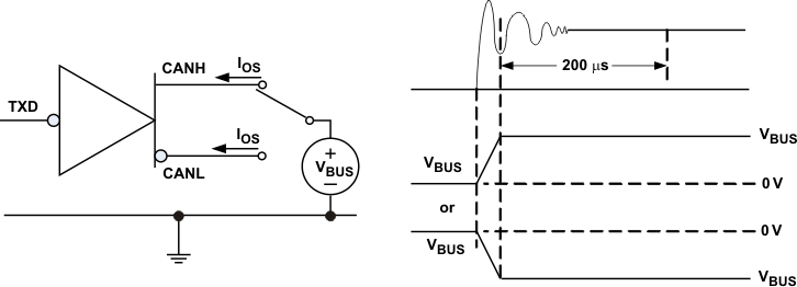
Figure 11. Driver Short Circuit Current Test and Measurement
千亿体育app官网登录(中国)官方网站IOS/安卓通用版/手机APP
|
米乐app下载官网(中国)|ios|Android/通用版APP最新版
|
米乐|米乐·M6(中国大陆)官方网站
|
千亿体育登陆地址
|
华体会体育(中国)HTH·官方网站
|
千赢qy国际_全站最新版千赢qy国际V6.2.14安卓/IOS下载
|
18新利网v1.2.5|中国官方网站
|
bob电竞真人(中国官网)安卓/ios苹果/电脑版【1.97.95版下载】
|
千亿体育app官方下载(中国)官方网站IOS/安卓/手机APP下载安装
|