ZHCSAC4B October 2012 – November 2017 SN65HVD82
PRODUCTION DATA.
7 Parameter Measurement Information
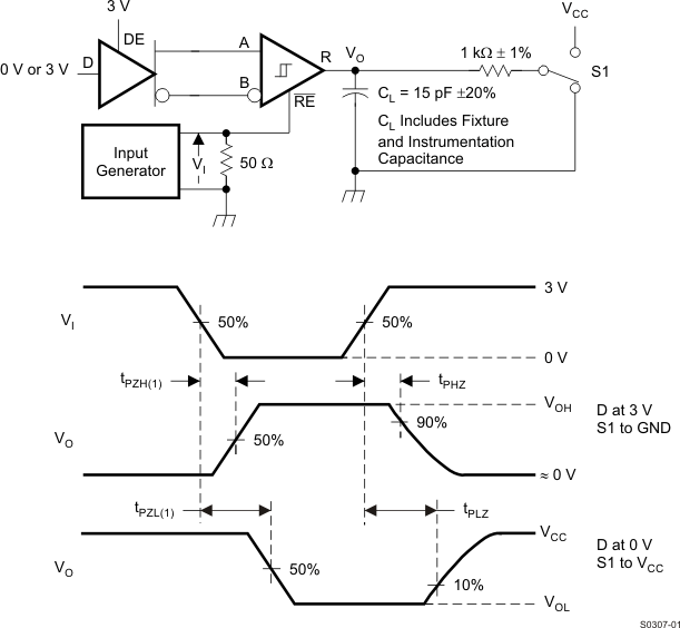
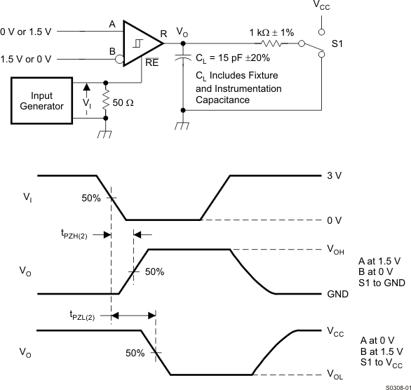
Input generator rate is 100 kbps, 50% duty cycle, rise and fall times less than 6 nsec, output impedance 50 Ω.
 Figure 5. Measurement of Driver Differential Output Voltage With Common-Mode Load
 Figure 6. Measurement of Driver Differential and Common-Mode Output With RS-485 Load
 Figure 7. Measurement of Driver Differential Output Rise and Fall Times and Propagation Delays

D at 3V to test non-inverting output, D at 0V to test inverting output.
Figure 8. Measurement of Driver Enable and Disable Times With Active High Output and Pull-Down Load

D at 0V to test non-inverting output, D at 3V to test inverting output.
Figure 9. Measurement of Driver Enable and Disable Times With Active Low Output and Pull-up Load
 Figure 10. Measurement of Receiver Output Rise and Fall Times and Propagation Delays
 Figure 11. Measurement of Receiver Enable/Disable Times With Driver Enabled
 Figure 12. Measurement of Receiver Enable Times With Driver Disabled