ZHCS686A January 2012 – March 2016 SN65LVCP114
PRODUCTION DATA.
- 1 特性
- 2 应用
- 3 说明
- 4 修订历史记录
- 5 说明 (续)
- 6 Pin Configuration and Functions
- 7 Specifications
- 8 Parameter Measurement Information
-
9 Detailed Description
- 9.1 Overview
- 9.2 Functional Block Diagram
- 9.3 Feature Description
- 9.4 Device Functional Modes
- 9.5 Programming
- 9.6
Register Maps
- 9.6.1
SN65LVCP114 Register Mapping Information
- 9.6.1.1 Register 0x00
- 9.6.1.2 Register 0x01
- 9.6.1.3 Register 0x02
- 9.6.1.4 Register 0x03
- 9.6.1.5 Register 0x04
- 9.6.1.6 Register 0x06
- 9.6.1.7 Register 0x07
- 9.6.1.8 Register 0x08
- 9.6.1.9 Register 0x0A
- 9.6.1.10 Register 0x0B
- 9.6.1.11 Register 0x0C
- 9.6.1.12 Register 0x0D
- 9.6.1.13 Register 0x0F
- 9.6.1.14 Register 0x10
- 9.6.1.15 Register 0x11
- 9.6.1.16 Register 0x12
- 9.6.1.17 Register Descriptions
- 9.6.1
SN65LVCP114 Register Mapping Information
- 10Application and Implementation
- 11Power Supply Recommendations
- 12Layout
- 13器件和文档支持
- 14机械、封装和可订购信息
1 特性
- 四路 2:1 多路复用器和 1:2 多路信号分离器
- 高达 14.2Gbps 串行数据速率的多速率运行
- 线性接收器均衡增加了判决反馈均衡器系统级上的容限
- 带宽:18GHz,典型值
- 每路 P/N对反转
- 端口或者单路开关
- 低功率:每通道 150mW,典型值
- 所有 3 个端口上的本地环回模式
- GPIO 之外的I2C 控制
- 输出线路侧端口数据到结构两侧端口的 DIAG 模式
- 2.5V 或 3.3V 单电源
- 塑料球状引脚栅格阵列 (PBGA) 封装 12mm × 12mm × 1mm,0.8-mm 端子脚距
- 到 100Ω PCB 传输线路的出色阻抗匹配
- 小封装尺寸节省了主板基板面空间
- 可调输出摆幅提供了灵活的电磁干扰 (EMI) 和串扰控制
- 低功率
- 凭借链路训练透明 功能 支持 10GBASE-KR 应用
2 应用
- 电信和数据通信的高速冗余开关
- 10G-KR,16GFC 的底板互连
3 说明
SN65LVCP114 器件是一款异步、与协议无关、低延迟四路多路复用器、线性转接驱动器,针对在速度高达 14.2Gbps 的系统中使用进行了优化。此器件在背板和有源线缆 应用应用中对通道损失进行线性补偿。SN65LVCP114 线性再驱动器的架构设计与使用判决反馈均衡器 (DFE) 技术来实现数字均衡的 ASIC 或者现场可编程门阵列 (FPGA) 米6体育平台手机版_好二三四一起高效工作。SN65LVCP114 复用器,线性再驱动器保持所接收到数据的完整性(结构)以优化 DFE 和系统性能。SN65LVCP114 在提供一个低功率复用器-解复用器,线性再驱动器解决方案的同时扩展了 DFE 的有效性。
器件信息(1)
| 器件型号 | 封装 | 封装尺寸(标称值) |
|---|---|---|
| SN65LVCP114 | NFBGA (167) | 12.00mm x 12.00mm |
- 如需了解所有可用封装,请参阅数据表末尾的可订购米6体育平台手机版_好二三四附录。
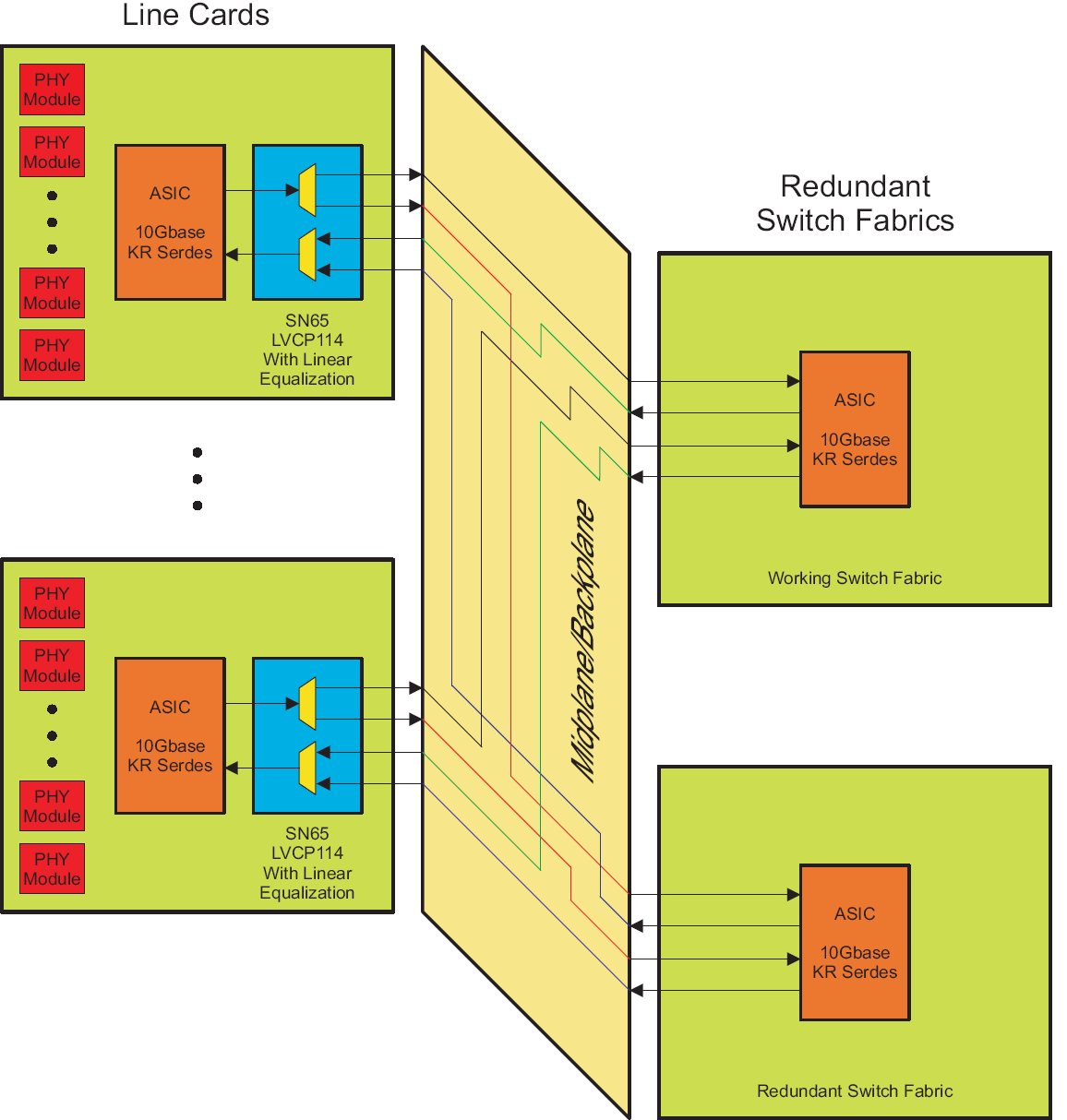
SN65LVCP114 典型实施方案
