ZHCSP29A October   2021  – December 2021 SN74HCT595

PRODUCTION DATA  

  1. 特性
  2. 应用
  3. 说明
  4. Revision History
  5. Pin Configuration and Functions
  6. Specifications
    1. 6.1 Absolute Maximum Ratings
    2. 6.2 ESD Ratings
    3. 6.3 Recommended Operating Conditions
    4. 6.4 Thermal Information
    5. 6.5 Electrical Characteristics
    6. 6.6 Timing Characteristics
    7. 6.7 Switching Characteristics
    8.     14
    9. 6.8 Typical Characteristics
  7. Parameter Measurement Information
  8. Detailed Description
    1. 8.1 Functional Block Diagram
    2. 8.2 Feature Description
      1. 8.2.1 Balanced CMOS 3-State Outputs
      2. 8.2.2 Balanced CMOS Push-Pull Outputs
      3. 8.2.3 TTL-Compatible CMOS Inputs
      4. 8.2.4 Latching Logic
      5. 8.2.5 Clamp Diode Structure
    3. 8.3 Device Functional Modes
  9. Application and Implementation
    1. 9.1 Application Information
    2. 9.2 Typical Application
      1. 9.2.1 Design Requirements
        1. 9.2.1.1 Power Considerations
        2. 9.2.1.2 Input Considerations
        3. 9.2.1.3 Output Considerations
      2. 9.2.2 Detailed Design Procedure
      3. 9.2.3 Application Curve
  10. 10Power Supply Recommendations
  11. 11Layout
    1. 11.1 Layout Guidelines
    2. 11.2 Layout Example
  12. 12Device and Documentation Support
    1. 12.1 Documentation Support
      1. 12.1.1 Related Documentation
    2. 12.2 接收文档更新通知
    3. 12.3 支持资源
    4. 12.4 Trademarks
    5. 12.5 Electrostatic Discharge Caution
    6. 12.6 术语表
  13. 13Mechanical, Packaging, and Orderable Information

封装选项

机械数据 (封装 | 引脚)
散热焊盘机械数据 (封装 | 引脚)
订购信息

说明

SN74HCT595 器件包含对 8 位 D 类存储寄存器进行馈送的 8 位串行输入、并行输出移位寄存器。存储寄存器具有并行三态输出。移位寄存器和存储寄存器分别有单独的时钟。移位寄存器具有一个直接覆盖清零 (SRCLR) 的串行 (SER) 输入和一个串行输出 (QH'),以用于级联。当输出使能端 (OE) 输入为高电平时,存储寄存器输出处于高阻抗状态。内部寄存器数据和串行输出 (QH') 不受 OE 端输入的影响。

器件信息(1)
器件型号封装封装尺寸(标称值)
SN74HCT595PWTSSOP (16)5.00mm × 4.40mm
如需了解所有可用封装,请参阅数据表末尾的可订购米6体育平台手机版_好二三四附录。
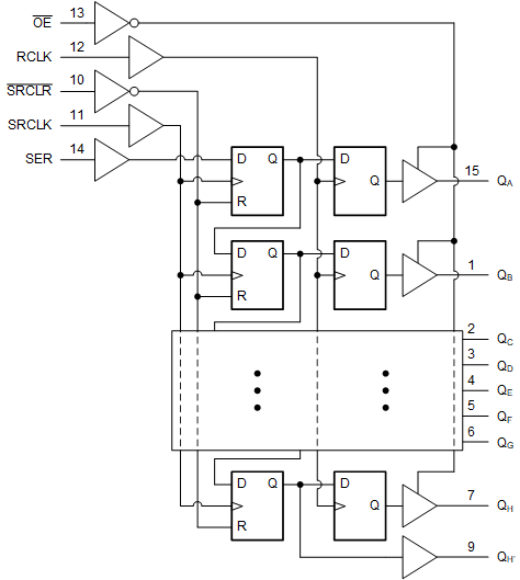
GUID-20211015-SS0I-66P0-J2PR-6DVV9SDRTXZD-low.gif逻辑图(正逻辑)