SCES470F August 2003 – August 2015 SN74LVC3G17
PRODUCTION DATA.
- 1 Features
- 2 Applications
- 3 Description
- 4 Revision History
- 5 Pin Configuration and Functions
- 6 Specifications
- 7 Parameter Measurement Information
- 8 Detailed Description
- 9 Application and Implementation
- 10Power Supply Recommendations
- 11Layout
- 12Device and Documentation Support
- 13Mechanical, Packaging, and Orderable Information
封装选项
请参考 PDF 数据表获取器件具体的封装图。
机械数据 (封装 | 引脚)
- DCU|8
- YZP|8
- DCT|8
散热焊盘机械数据 (封装 | 引脚)
订购信息
8 Detailed Description
8.1 Overview
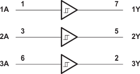
This triple Schmitt-trigger buffer is designed for 1.65-V to 5.5-V VCC operation. The SN74LVC3G17 device contains three buffers and performs the Boolean function Y = A. The device functions as three independent buffers but, because of Schmitt action, it may have different input threshold levels for positive-going (VT+) and negative-going (VT–) signals. This device is fully specified for partial-power-down applications using Ioff. The Ioff circuitry disables the outputs, preventing damaging current backflow through the device when it is powered down. NanoFree™ package technology is a major breakthrough in IC packaging concepts, using the die as the package.
8.2 Functional Block Diagram

8.3 Feature Description
SN74LVC3G17 is available in NanoFree package. NanoFree is a major breakthrough in IC packaging concepts, it is a bare die package developed for applications that require the smallest possible package. The device supports 5-V VCC Operation. All Inputs accept voltages up to 5.5 V. ±24-mA Output Drive at 3.3 V. The maximum time propagation delay (tpd ) is 5.4 ns at 3.3 V. Low Power Consumption, 10-μA Max ICC. Typical output ground bounce (VOLP ) and Output VOH Undershoot (VOHV). This device is fully specified for partial-powerdown applications using Ioff. The Ioff feature ensures that damaging current will not backflow through the device when it is powered down. The SN74LVC3G17 device has isolation during power off. Ioff supports live insertion, partial-power-down mode and back drive protection. The device is latch-up resistant with 100 mA exceeding the JESD 78 standard, class II, providing protection from destruction due to latch-up. This device is protected against electrostatic discharge. It is tested per JESD 22 using 2000-V human-body model (A114-B), 200-V machine model (A115-A), and 1000-V charged-device model (C101).
8.4 Device Functional Modes
Table 1 lists the functional modes of the SN74LVC3G17.
Table 1. Function Table
| INPUT A |
OUTPUT Y |
|---|---|
| H | H |
| L | L |