ZHCSMU9A December 2020 – September 2021 TAS2764
PRODUCTION DATA
- 1 特性
- 2 应用
- 3 说明
- 4 Revision History
- 5 Pin Configuration and Functions
- 6 Specifications
- 7 Parameter Measurement Information
-
8 Detailed Description
- 8.1 Overview
- 8.2 Functional Block Diagram
- 8.3 Feature Description
- 8.4
Device Functional Modes
- 8.4.1 TDM Port
- 8.4.2
Playback Signal Path
- 8.4.2.1 High Pass Filter
- 8.4.2.2 Amplifier Inversion
- 8.4.2.3 Digital Volume Control and Amplifier Output Level
- 8.4.2.4 VBAT1S Supply
- 8.4.2.5 Low Voltage Signaling (LVS)
- 8.4.2.6 Y-Bridge
- 8.4.2.7 Noise Gate
- 8.4.2.8 Supply Tracking Limiter with Brown Out Prevention
- 8.4.2.9 Inter Chip Gain Alignment
- 8.4.2.10 Class-D Settings
- 8.4.3 SAR ADC
- 8.4.4 Current and Voltage (IV) Sense
- 8.4.5 Post Filter Feed-Back (PFFB)
- 8.4.6 Load Diagnostics
- 8.4.7 Thermal Foldback
- 8.4.8 Over Power Protection
- 8.4.9 Clocks and PLL
- 8.4.10 Echo Reference
- 8.5 Operational Modes
- 8.6 Faults and Status
- 8.7 Power Sequencing Requirements
- 8.8 Digital Input Pull Downs
- 8.9
Register Map
- 8.9.1 Register Summary Table Page=0x00
- 8.9.2 Register Summary Table Page=0x01
- 8.9.3 Register Summary Table Page=0x04
- 8.9.4 PAGE (page=0x00 address=0x00) [reset=00h]
- 8.9.5 SW_RESET (page=0x00 address=0x01) [reset=00h]
- 8.9.6 MODE_CTRL (page=0x00 address=0x02) [reset=1Ah]
- 8.9.7 CHNL_0 (page=0x00 address=0x03) [reset=28h]
- 8.9.8 DC_BLK0 (page=0x00 address=0x04) [reset=21h]
- 8.9.9 DC_BLK1 (page=0x00 address=0x05) [reset=41h]
- 8.9.10 MISC_CFG1 (page=0x00 address=0x06) [reset=00h]
- 8.9.11 MISC_CFG2 (page=0x00 address=0x07) [reset=20h]
- 8.9.12 TDM_CFG0 (page=0x00 address=0x08) [reset=09h]
- 8.9.13 TDM_CFG1 (page=0x00 address=0x09) [reset=02h]
- 8.9.14 TDM_CFG2 (page=0x00 address=0x0A) [reset=0Ah]
- 8.9.15 LIM_MAX_ATTN (page=0x00 address=0x0B) [reset=80h]
- 8.9.16 TDM_CFG3 (page=0x00 address=0x0C) [reset=10h]
- 8.9.17 TDM_CFG4 (page=0x00 address=0x0D) [reset=13h]
- 8.9.18 TDM_CFG5 (page=0x00 address=0x0E) [reset=42h]
- 8.9.19 TDM_CFG6 (page=0x00 address=0x0F) [reset=40h]
- 8.9.20 TDM_CFG7 (page=0x00 address=0x10) [reset=04h]
- 8.9.21 TDM_CFG8 (page=0x00 address=0x11) [reset=05h]
- 8.9.22 TDM_CFG9 (page=0x00 address=0x12) [reset=06h]
- 8.9.23 TDM_CFG10 (page=0x00 address=0x13) [reset=08h]
- 8.9.24 TDM_CFG11 (page=0x00 address=0x14) [reset=0Ah]
- 8.9.25 ICC_CNFG2 (page=0x00 address=0x15) [reset=00h]
- 8.9.26 TDM_CFG12 (page=0x00 address=0x16) [reset=12h]
- 8.9.27 ICLA_CFG0 (page=0x00 address=0x17) [reset=0Ch]
- 8.9.28 ICLA_CFG1 (page=0x00 address=0x18) [reset=00h]
- 8.9.29 DG_0 (page=0x00 address=0x19) [reset=0Dh]
- 8.9.30 DVC (page=0x00 address=0x1A) [reset=00h]
- 8.9.31 LIM_CFG0 (page=0x00 address=0x1B) [reset=22h]
- 8.9.32 LIM_CFG1 (page=0x00 address=0x1C) [reset=32h]
- 8.9.33 BOP_CFG0 (page=0x00 address=0x1D) [reset=40h]
- 8.9.34 BOP_CFG1 (page=0x00 address=0x1E) [reset=32h]
- 8.9.35 BOP_CFG2 (page=0x00 address=0x1F) [reset=02h]
- 8.9.36 BOP_CFG3 (page=0x00 address=0x20) [reset=06h]
- 8.9.37 BOP_CFG4 (page=0x00 address=0x21) [reset=2Ch]
- 8.9.38 BOP_CFG5 (page=0x00 address=0x22) [reset=4Ch]
- 8.9.39 BOP_CFG6 (page=0x00 address=0x23) [reset=20h]
- 8.9.40 BOP_CFG7 (page=0x00 address=0x24) [reset=02h]
- 8.9.41 BOP_CFG8 (page=0x00 address=0x25) [reset=06h]
- 8.9.42 BOP_CFG9 (page=0x00 address=0x26) [reset=32h]
- 8.9.43 BOP_CFG10 (page=0x00 address=0x27) [reset=46h]
- 8.9.44 BOP_CFG11 (page=0x00 address=0x28) [reset=20h]
- 8.9.45 BOP_CFG12 (page=0x00 address=0x29) [reset=02h]
- 8.9.46 BOP_CFG13 (page=0x00 address=0x2A) [reset=06h]
- 8.9.47 BOP_CFG14 (page=0x00 address=0x2B) [reset=38h]
- 8.9.48 BOP_CFG15 (page=0x00 address=0x2C) [reset=40h]
- 8.9.49 BOP_CFG17 (page=0x00 address=0x2D) [reset=20h]
- 8.9.50 BOP_CFG18 (page=0x00 address=0x2E) [reset=02h]
- 8.9.51 BOP_CFG19 (page=0x00 address=0x2F) [reset=06h]
- 8.9.52 BOP_CFG20 (page=0x00 address=0x30) [reset=3Eh]
- 8.9.53 BOP_CFG21 (page=0x00 address=0x31) [reset=37h]
- 8.9.54 BOP_CFG22 (page=0x00 address=0x32) [reset=20h]
- 8.9.55 BOP_CFG23 (page=0x00 address=0x33) [reset=FFh]
- 8.9.56 BOP_CFG24 (page=0x00 address=0x34) [reset=E6h]
- 8.9.57 NG_CFG0 (page=0x00 address=0x35) [reset=BDh]
- 8.9.58 NG_CFG1 (page=0x00 address=0x36) [reset=ADh]
- 8.9.59 LVS_CFG0 (page=0x00 address=0x37) [reset=A8h]
- 8.9.60 DIN_PD (page=0x00 address=0x38) [reset=03h]
- 8.9.61 IO_DRV0 (page=0x00 address=0x39) [reset=FFh]
- 8.9.62 IO_DRV1 (page=0x00 address=0x3A) [reset=FFh]
- 8.9.63 INT_MASK0 (page=0x00 address=0x3B) [reset=FCh]
- 8.9.64 INT_MASK1 (page=0x00 address=0x3C) [reset=BEh]
- 8.9.65 INT_MASK4 (page=0x00 address=0x3D) [reset=DFh]
- 8.9.66 INT_MASK2 (page=0x00 address=0x40) [reset=F6h]
- 8.9.67 INT_MASK3 (page=0x00 address=0x41) [reset=00h]
- 8.9.68 INT_LIVE0 (page=0x00 address=0x42) [reset=00h]
- 8.9.69 INT_LIVE1 (page=0x00 address=0x43) [reset=00h]
- 8.9.70 INT_LIVE1_0 (page=0x00 address=0x44) [reset=00h]
- 8.9.71 INT_LIVE2 (page=0x00 address=0x47) [reset=00h]
- 8.9.72 INT_LIVE3 (page=0x00 address=0x48) [reset=00h]
- 8.9.73 INT_LTCH0 (page=0x00 address=0x49) [reset=00h]
- 8.9.74 INT_LTCH1 (page=0x00 address=0x4A) [reset=00h]
- 8.9.75 INT_LTCH1_0 (page=0x00 address=0x4B) [reset=00h]
- 8.9.76 INT_LTCH2 (page=0x00 address=0x4F) [reset=00h]
- 8.9.77 INT_LTCH3 (page=0x00 address=0x50) [reset=00h]
- 8.9.78 INT_LTCH4 (page=0x00 address=0x51) [reset=00h]
- 8.9.79 VBAT_MSB (page=0x00 address=0x52) [reset=00h]
- 8.9.80 VBAT_LSB (page=0x00 address=0x53) [reset=00h]
- 8.9.81 PVDD_MSB (page=0x00 address=0x54) [reset=00h]
- 8.9.82 PVDD_LSB (page=0x00 address=0x55) [reset=00h]
- 8.9.83 TEMP (page=0x00 address=0x56) [reset=00h]
- 8.9.84 INT_CLK_CFG (page=0x00 address=0x5C) [reset=19h]
- 8.9.85 MISC_CFG3 (page=0x00 address=0x5D) [reset=80h]
- 8.9.86 CLOCK_CFG (page=0x00 address=0x60) [reset=0Dh]
- 8.9.87 IDLE_IND (page=0x00 address=0x63) [reset=48]
- 8.9.88 MISC_CFG4 (page=0x00 address=0x65) [reset=08]
- 8.9.89 TG_CFG0 (page=0x00 address=0x67) [reset=00h]
- 8.9.90 CLK_CFG (page=0x00 address=0x68) [reset=7Fh]
- 8.9.91 LV_EN_CFG (page=0x00 address=0x6A) [reset=12h]
- 8.9.92 NG_CFG2 (page=0x00 address=0x6B) [reset=01h]
- 8.9.93 NG_CFG3 (page=0x00 address=0x6C) [reset=00h]
- 8.9.94 NG_CFG4 (page=0x00 address=0x6D) [reset=00h]
- 8.9.95 NG_CFG5 (page=0x00 address=0x6E) [reset=1Ah]
- 8.9.96 NG_CFG6 (page=0x00 address=0x6F) [reset=00h]
- 8.9.97 NG_CFG7 (page=0x00 address=0x70) [reset=96h]
- 8.9.98 PVDD_UVLO (page=0x00 address=0x71) [reset=00h]
- 8.9.99 DAC_MOD_RST (page=0x00 address=0x76) [reset=02h]
- 8.9.100 REV_ID (page=0x00 address=0x7D) [reset=30h]
- 8.9.101 I2C_CKSUM (page=0x00 address=0x7E) [reset=00h]
- 8.9.102 BOOK (page=0x00 address=0x7F) [reset=00h]
- 8.9.103 LSR (page=0x01 address=0x19) [reset=40h]
- 8.9.104 SDOUT_HIZ_1 (page=0x01 address=0x3D) [reset=00h]
- 8.9.105 SDOUT_HIZ_2 (page=0x01 address=0x3E) [reset=00h]
- 8.9.106 SDOUT_HIZ_3 (page=0x01 address=0x3F) [reset=00h]
- 8.9.107 SDOUT_HIZ_4 (page=0x01 address=0x40) [reset=00h]
- 8.9.108 SDOUT_HIZ_5 (page=0x01 address=0x41) [reset=00h]
- 8.9.109 SDOUT_HIZ_6 (page=0x01 address=0x42) [reset=00h]
- 8.9.110 SDOUT_HIZ_7 (page=0x01 address=0x43) [reset=00h]
- 8.9.111 SDOUT_HIZ_8 (page=0x01 address=0x44) [reset=00h]
- 8.9.112 SDOUT_HIZ_9 (page=0x01 address=0x45) [reset=00h]
- 8.9.113 TG_EN (page=0x01 address=0x47) [reset=ABh]
- 8.9.114 DG_DC_VAL1 (page=0x04 address=0x08) [reset=40h]
- 8.9.115 DG_DC_VAL2 (page=0x04 address=0x09) [reset=26h]
- 8.9.116 DG_DC_VAL3 (page=0x04 address=0x0A) [reset=40h]
- 8.9.117 DC_DG_VAL4 (page=0x04 address=0x0B) [reset=00h]
- 8.9.118 LIM_TH_MAX1 (page=0x04 address=0x0C) [reset=68h]
- 8.9.119 LIM_TH_MAX2 (page=0x04 address=0x0D) [reset=00h]
- 8.9.120 LIM_TH_MAX3 (page=0x04 address=0x0E) [reset=00h]
- 8.9.121 LIM_TH_MAX4 (page=0x04 address=0x0F) [reset=00h]
- 8.9.122 LIM_TH_MIN1 (page=0x04 address=0x10) [reset=28h]
- 8.9.123 LIM_TH_MIN2 (page=0x04 address=0x11) [reset=00h]
- 8.9.124 LIM_TH_MIN3 (page=0x04 address=0x12) [reset=00h]
- 8.9.125 LIM_TH_MIN4 (page=0x04 address=0x13) [reset=00h]
- 8.9.126 LIM_INF_PT1 (page=0x04 address=0x14) [reset=56h]
- 8.9.127 LIM_INF_PT2 (page=0x04 address=0x15) [reset=66h]
- 8.9.128 LIM_INF_PT3 (page=0x04 address=0x16) [reset=66h]
- 8.9.129 LIM_INF_PT4 (page=0x04 address=0x17) [reset=00h]
- 8.9.130 LIM_SLOPE1 (page=0x04 address=0x18) [reset=10h]
- 8.9.131 LIM_SLOPE2 (page=0x04 address=0x19) [reset=00h]
- 8.9.132 LIM_SLOPE3 (page=0x04 address=0x1A) [reset=00h]
- 8.9.133 LIM_SLOPE4 (page=0x04 address=0x1B) [reset=00h]
- 8.9.134 TF_HLD1 (page=0x04 address=0x1C) [reset=00h]
- 8.9.135 TF_HLD2 (page=0x04 address=0x1D) [reset=03h]
- 8.9.136 TF_HLD3 (page=0x04 address=0x1E) [reset=E8h]
- 8.9.137 TF_HLD4 (page=0x04 address=0x1F) [reset=00h]
- 8.9.138 TF_RLS1 (page=0x04 address=0x20) [reset=40h]
- 8.9.139 TF_RLS2 (page=0x04 address=0x21) [reset=12h]
- 8.9.140 TF_RLS3 (page=0x04 address=0x22) [reset=E0h]
- 8.9.141 TF_RLS4 (page=0x04 address=0x23) [reset=00h]
- 8.9.142 TF_SLOPE1 (page=0x04 address=0x24) [reset=04h]
- 8.9.143 TF_SLOPE2 (page=0x04 address=0x25) [reset=08h]
- 8.9.144 TF_SLOPE3 (page=0x04 address=0x26) [reset=89h]
- 8.9.145 TF_SLOPE4 (page=0x04 address=0x27) [reset=00h]
- 8.9.146 TF_TEMP_TH1 (page=0x04 address=0x28) [reset=39h]
- 8.9.147 TF_TEMP_TH2 (page=0x04 address=0x29) [reset=80h]
- 8.9.148 TF_TEMP_TH3 (page=0x04 address=0x2A) [reset=00h]
- 8.9.149 TF_TEMP_TH4 (page=0x04 address=0x2B) [reset=00h]
- 8.9.150 TF_MAX_ATTN1 (page=0x04 address=0x2C) [reset=2Dh]
- 8.9.151 TF_MAX_ATTN2 (page=0x04 address=0x2D) [reset=6Ah]
- 8.9.152 TF_MAX_ATTN3 (page=0x04 address=0x2E) [reset=86h]
- 8.9.153 TF_MAX_ATTN4 (page=0x04 address=0x2F) [reset=00h]
- 8.9.154 LD_CFG0 (page=0x04 address=0x40) [reset=02h]
- 8.9.155 LD_CFG1 (page=0x04 address=0x41) [reset=ADh]
- 8.9.156 LD_CFG2 (page=0x04 address=0x42) [reset=B7h]
- 8.9.157 LD_CFG3 (page=0x04 address=0x43) [reset=00h]
- 8.9.158 LD_CFG4 (page=0x04 address=0x44) [reset=00h]
- 8.9.159 LD_CFG5 (page=0x04 address=0x45) [reset=1Bh]
- 8.9.160 LD_CFG6 (page=0x04 address=0x46) [reset=6Eh]
- 8.9.161 LD_CFG7 (page=0x04 address=0x47) [reset=00h]
- 8.9.162 CLD_EFF_1 (page=0x04 address=0x48) [reset=6Ch]
- 8.9.163 CLD_EFF_2 (page=0x04 address=0x49) [reset=CCh]
- 8.9.164 CLD_EFF_3 (page=0x04 address=0x4A) [reset=CDh]
- 8.9.165 CLD_EFF_4 (page=0x04 address=0x4B) [reset=00h]
- 8.9.166 LDG_RES1 (page=0x04 address=0x4C) [reset=00h]
- 8.9.167 LDG_RES2 (page=0x04 address=0x4D) [reset=00h]
- 8.9.168 LDG_RES3 (page=0x04 address=0x4E) [reset=00h]
- 8.9.169 LDG_RES4 (page=0x04 address=0x4F) [reset=00h]
- 8.10 SDOUT Equations
- 9 Application and Implementation
- 10Initialization Set Up
- 11Power Supply and I2C Recommendations
- 12Layout
- 13Device and Documentation Support
- 14Mechanical, Packaging, and Orderable Information
8.4.2.8.1 Supply Tracking Limiter
The TAS2764 monitors the PVDD supply voltage and the audio signal to automatically decrease gain when the audio signal peaks exceed a programmable threshold. This helps prevent clipping and extends playback time through end of charge battery conditions. The limiter threshold can be configured to track PVDD below a programmable inflection point with a programmable slope. A minimum threshold sets the limit of threshold reduction from PVDD tracking.
The limiter is enabled by setting the LIM_EN bit register to high.
Configurable attack rate, hold time and release rate are provided to shape the dynamic response of the limiter (LIM_ATK_RT[3:0], LIM_HLD_TM[2:0] and LIM_RLS_RT [3:0] register bits).
A maximum level of attenuation applied by the limiter is configurable via the LIM_MAX_ATTN[3:0] register bits. If the limiter mode is attacking and if it reaches the maximum attenuation, gain will not be reduced any further.
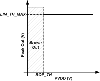
The limiter begins reducing gain when the output signal level is greater than the limiter threshold. The limiter can be configured to track PVDD below a programmable inflection point with a minimum threshold value. Figure 8-6 below shows the limiter configured to limit to a constant level regardless of PVDD level. To achieve this behavior, set the limiter maximum threshold to the desired level via the LIM_TH_MAX[31:0] register bits. Set the limiter inflection point (register bits LIM_INF_PT[31:0]) below the minimum allowable PVDD setting. The limiter minimum threshold, set by register bits LIM_TH_MIN[31:0], does not impact limiter behavior in this use case.
 Figure 8-6 Limiter with Fixed
Threshold
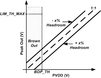
 Figure 8-8 Limiter with Dynamic
Threshold
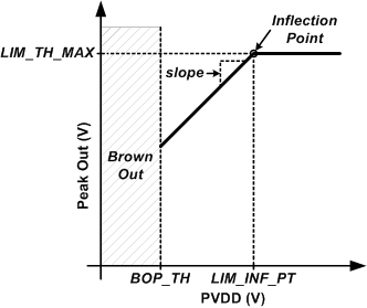
 Figure 8-7 Limiter with Inflection
Point
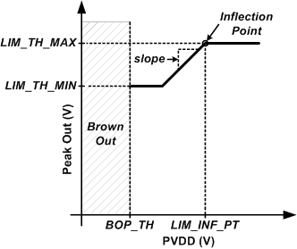
 Figure 8-9 Limiter with Inflection Point
and Minimum Threshold
Figure 8-9 Limiter with Inflection Point
and Minimum ThresholdFigure 8-7 shows how to configure the limiter to track PVDD below a threshold without a minimum threshold. Set the LIM_TH_MAX[31:0] register bits to the desired threshold and LIM_INF_PT[31:0] register bits to the desired inflection point where the limiter will begin reducing the threshold with PVDD. The LIM_SLOPE[31:0] register bits can be used to change the slope of the limiter tracking with PVDD. The default value of 1 V/V will reduce the threshold 1 V for every 1 V of drop in PVDD. More aggressive tracking slopes can be programmed if desired. Program the LIM_TH_MIN[31:0] bits below the minimum PVDD to prevent the limiter from having a minimum threshold reduction when tracking PVDD.
The limiter with a supply tracking slope can be configured in an alternate way. By setting LIM_HR_EN register bit to 1'b1 , a headroom can be specified as a percentage of the supply voltage using a 1V/V slope by setting LIM_DHR[4:0] register bits. For example if a headroom of -10% is specified, the peak output voltage will be set to be 10% higher than PVDD. In this use case presented in Figure 8-8 the limiting begins for signals above the supply voltage and will result in a fixed clipping. If a positive headroom of +10% is specified the peak output voltage will be dynamically set 10% below the current PVDD. In this use case the limiting will begin at signal levels lower than the supply voltage and prevent clipping from occurring.
To achieve a limiter that tracks PVDD only up to a minimum threshold, configure the limiter LIM_TH_MAX [31:0] and LIM_SLOPE[31:0] register bits as in the previous examples. Then additionally set the LIM_TH_MIN[31:0] register bits to the desired minimum threshold. Supply voltage below this minimum threshold will not continue to decrease the signal output voltage. This is shown in Figure 8-9.
By setting register bit LIM_DHYS_EN to low the limiter mechanism depends on settings for maximum/minimum thresholds, inflection point and slope. Once this bit is set high the limiter dynamic headroom is enabled.
When a BOP (Section 8.4.2.8.2) event occurs the limiter updates can be paused (LIM_PDB register bit set to 1'b1) until the BOP fully releases. This can be used to prevent undesired interactions between both protection systems.