ZHCSIA0A May 2018 – November 2018 TAS3251
PRODUCTION DATA.
- 1 特性
- 2 应用
- 3 说明
- 4 修订历史记录
- 5 Device Comparison Table
- 6 Pin Configuration and Functions
-
7 Specifications
- 7.1 Absolute Maximum Ratings
- 7.2 ESD Ratings
- 7.3 Recommended Operating Conditions
- 7.4 Thermal Information
- 7.5 Amplifier Electrical Characteristics
- 7.6 DAC Electrical Characteristics
- 7.7 Audio Characteristics (BTL)
- 7.8 Audio Characteristics (PBTL)
- 7.9 MCLK Timing
- 7.10 Serial Audio Port Timing – Slave Mode
- 7.11 Serial Audio Port Timing – Master Mode
- 7.12 I2C Bus Timing –Standard
- 7.13 I2C Bus Timing –Fast
- 7.14 Timing Diagrams
- 7.15 Typical Characteristics
-
8 Detailed Description
- 8.1 Overview
- 8.2 Functional Block Diagram
- 8.3
Feature Description
- 8.3.1 Power-on-Reset (POR) Function
- 8.3.2 Enable Device
- 8.3.3 DAC and DSP Clocking
- 8.3.4
Serial Audio Port
- 8.3.4.1 Clock Master Mode from Audio Rate Master Clock
- 8.3.4.2 Clock Slave Mode with 4-Wire Operation (SCLK, MCLK, LRCK/FS, SDIN)
- 8.3.4.3 Clock Slave Mode with SCLK PLL to Generate Internal Clocks (3-Wire PCM)
- 8.3.4.4 Serial Audio Port – Data Formats and Bit Depths
- 8.3.4.5 Input Signal Sensing (Power-Save Mode)
- 8.3.5 Volume Control
- 8.3.6 SDOUT Port and Hardware Control Pin
- 8.3.7 I2C Communication Port
- 8.3.8 Pop and Click Free Startup and Shutdown
- 8.3.9 Integrated Oscillator for Output Power Stage
- 8.3.10
Device Output Stage Protection System
- 8.3.10.1 Error Reporting
- 8.3.10.2 Overload and Short Circuit Current Protection
- 8.3.10.3 Signal Clipping and Pulse Injector
- 8.3.10.4 DC Speaker Protection
- 8.3.10.5 Pin-to-Pin Short Circuit Protection (PPSC)
- 8.3.10.6 Overtemperature Protection OTW and OTE
- 8.3.10.7 Undervoltage Protection (UVP) and Power-on Reset (POR)
- 8.3.10.8 Fault Handling
- 8.3.10.9 Output Power Stage Reset
- 8.3.11
Initialization, Startup and Shutdown
- 8.3.11.1 Power Up and Startup Sequence
- 8.3.11.2 Power Down and Shutdown Sequence
- 8.3.11.3 Device Mute
- 8.3.11.4 Device Unmute
- 8.3.11.5 Device Reset
- 8.3.11.6 Mute with DAC_MUTE or Clock Error
- 8.3.11.7 Mute using Serial Audio Port Clock
- 8.3.11.8 Muting before an Unplanned Shutdown with DAC_MUTE
- 8.3.11.9 Output Power Stage Startup Timing
- 8.4 Device Functional Modes
- 8.5
Programming
- 8.5.1 Audio Processing Features
- 8.5.2 Processing Block Description
- 8.5.3 Other Processing Block Features
- 8.5.4 Checksum
- 8.6
Register Maps
- 8.6.1
Registers - Page 0
- 8.6.1.1 Register 1 (0x01)
- 8.6.1.2 Register 2 (0x02)
- 8.6.1.3 Register 3 (0x03)
- 8.6.1.4 Register 4 (0x04)
- 8.6.1.5 Register 6 (0x06)
- 8.6.1.6 Register 7 (0x07)
- 8.6.1.7 Register 8 (0x08)
- 8.6.1.8 Register 9 (0x09)
- 8.6.1.9 Register 12 (0x0C)
- 8.6.1.10 Register 13 (0x0D)
- 8.6.1.11 Register 14 (0x0E)
- 8.6.1.12 Register 15 (0x0F)
- 8.6.1.13 Register 16 (0x10)
- 8.6.1.14 Register 17 (0x11)
- 8.6.1.15 Register 18 (0x12)
- 8.6.1.16 Register 20 (0x14)
- 8.6.1.17 Register 21 (0x15)
- 8.6.1.18 Register 22 (0x16)
- 8.6.1.19 Register 23 (0x17)
- 8.6.1.20 Register 24 (0x18)
- 8.6.1.21 Register 27 (0x1B)
- 8.6.1.22 Register 28 (0x1C)
- 8.6.1.23 Register 29 (0x1D)
- 8.6.1.24 Register 30 (0x1E)
- 8.6.1.25 Register 32 (0x20)
- 8.6.1.26 Register 33 (0x21)
- 8.6.1.27 Register 34 (0x22)
- 8.6.1.28 Register 37 (0x25)
- 8.6.1.29 Register 40 (0x28)
- 8.6.1.30 Register 41 (0x29)
- 8.6.1.31 Register 42 (0x2A)
- 8.6.1.32 Register 43 (0x2B)
- 8.6.1.33 Register 44 (0x2C)
- 8.6.1.34 Register 59 (0x3B)
- 8.6.1.35 Register 60 (0x3C)
- 8.6.1.36 Register 61 (0x3D)
- 8.6.1.37 Register 62 (0x3E)
- 8.6.1.38 Register 63 (0x3F)
- 8.6.1.39 Register 64 (0x40)
- 8.6.1.40 Register 65 (0x41)
- 8.6.1.41 Register 67 (0x43)
- 8.6.1.42 Register 68 (0x44)
- 8.6.1.43 Register 69 (0x45)
- 8.6.1.44 Register 70 (0x46)
- 8.6.1.45 Register 71 (0x47)
- 8.6.1.46 Register 72 (0x48)
- 8.6.1.47 Register 73 (0x49)
- 8.6.1.48 Register 74 (0x4A)
- 8.6.1.49 Register 75 (0x4B)
- 8.6.1.50 Register 76 (0x4C)
- 8.6.1.51 Register 78 (0x4E)
- 8.6.1.52 Register 79 (0x4F)
- 8.6.1.53 Register 85 (0x55)
- 8.6.1.54 Register 86 (0x56)
- 8.6.1.55 Register 87 (0x57)
- 8.6.1.56 Register 88 (0x58)
- 8.6.1.57 Register 91 (0x5B)
- 8.6.1.58 Register 92 (0x5C)
- 8.6.1.59 Register 93 (0x5D)
- 8.6.1.60 Register 94 (0x5E)
- 8.6.1.61 Register 95 (0x5F)
- 8.6.1.62 Register 108 (0x6C)
- 8.6.1.63 Register 119 (0x77)
- 8.6.1.64 Register 120 (0x78)
- 8.6.2 Registers - Page 1
- 8.6.1
Registers - Page 0
-
9 Application and Implementation
- 9.1
Typical Applications
- 9.1.1 Stereo, Bridge Tied Load (BTL) Application
- 9.1.2 Mono, Parallel Bridge-Tied Load (PBTL) Application
- 9.1.3 Design Requirements
- 9.1.4 Detailed Design Procedure
- 9.1.5 Two TAS3251 Device Configurations
- 9.1.6 Three or More TAS3251 Device Configurations
- 9.1.7 Application Curves
- 9.1
Typical Applications
- 10Power Supply Recommendations
- 11Layout
- 12器件和文档支持
- 13机械、封装和可订购信息
8.3.4.4.1 Data Formats and Master/Slave Modes of Operation
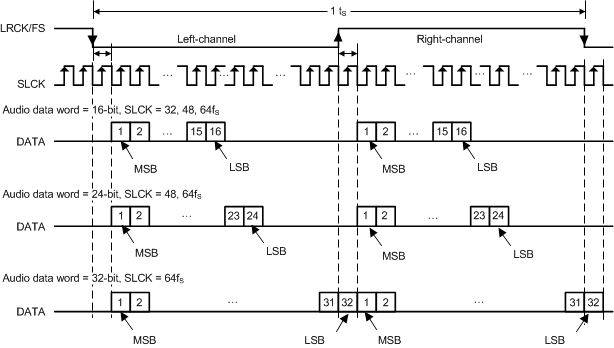
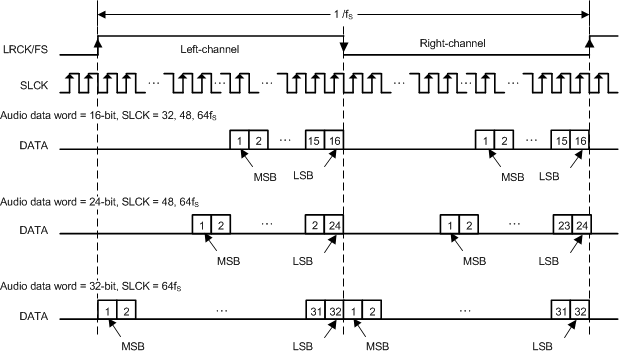
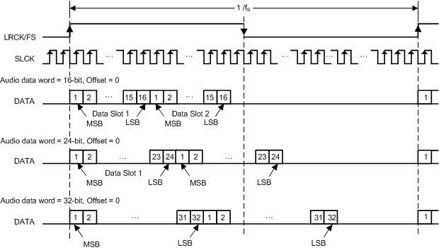
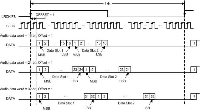
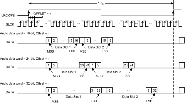
The TAS3251 device supports industry-standard audio data formats, including standard I2S and left-justified. Data formats are selected via Register (P0-R40). All formats require binary two's complement, MSB-first audio data; up to 32-bit audio data is accepted. The data formats are detailed in Figure 24 through Figure 29.
The TAS3251 device also supports right-justified and TDM/DSP data. I2S, LJ, RJ, and TDM/DSP are selected using Register (P0-R40). All formats require binary 2s complement, MSB-first audio data. Up to 32 bits are accepted. Default setting is I2S and 24 bit word length. The I2S slave timing is shown in Figure 3.
shows a detailed timing diagram for the serial audio interface.
In addition to acting as a I2S slave, the TAS3251 device can act as an I2S master, by generating SCLK and LRCK/FS as outputs from the MCLK input. Table 9 lists the registers used to place the device into Master or Slave mode. Please refer to theSerial Audio Port Timing – Master Mode section for serial audio Interface timing requirements in Master Mode. For Slave Mode timing, please refer to to the Serial Audio Port Timing – Slave Mode section.
Table 9. I2S Master Mode Registers
| REGISTER | FUNCTION |
|---|---|
| P0-R9-B0, B4, and B5 | I2S Master mode select |
| P0-R32-D[6:0] | SCLK divider and LRCK/FS divider |
| P0-R33-D[7:0] |
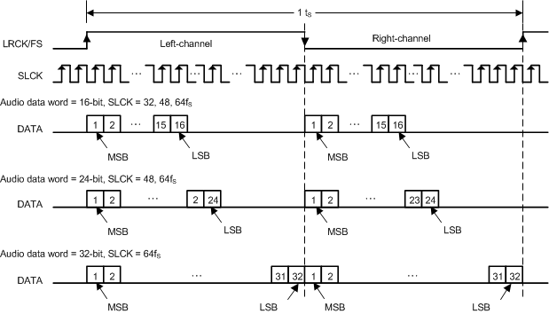 Figure 24. Left Justified Audio Data Format