ZHCSFW8 December 2016 TAS5414C
PRODUCTION DATA.
- 1 特性
- 2 应用
- 3 说明
- 4 修订历史记录
- 5 Pin Configuration and Functions
- 6 Specifications
-
7 Detailed Description
- 7.1 Overview
- 7.2 Functional Block Diagram
- 7.3 Feature Descption
- 7.4 Device Functional Modes
- 7.5 Programming
- 7.6
Register Maps
- 7.6.1 Register Summary
- 7.6.2 Registers
- 7.6.3 Fault Register 2 (0x01) Protection
- 7.6.4 Diagnostic Register 1 (0x02) Load Diagnostics
- 7.6.5 Diagnostic Register 2 (0x03) Load Diagnostics
- 7.6.6 External Status Register 1 (0x04) Fault Detection
- 7.6.7 External Status Register 2 (0x05) Output State of Individual Channels
- 7.6.8 External Status Register 3 (0x06) Play and Mute Modes
- 7.6.9 External Status Register 4 (0x07) Load Diagnostics
- 7.6.10 External Control Register 1 (0x08) Gain Select
- 7.6.11 External Control Register 2 (0x09) Overcurrent Control
- 7.6.12 External Control Register 3 (0x0A) Switching Frequency Select and Clip_OTW Configuration
- 7.6.13 External Control Register 4 (0x0B) Load Diagnostics and Master/Slave Control
- 7.6.14 External Control Register 5 (0x0C) Output Control
- 7.6.15 External Control Register 6 (0x0D) Output Control
- 7.6.16 External Control Register 7 (0x10) Miscellaneous Selection
- 7.6.17 External Status Register 5 (0x13) Overtemperature and Thermal Foldback Status
- 8 Application and Implementation
- 9 Power Supply Recommendations
- 10Layout
- 11器件和文档支持
- 12机械、封装和可订购信息
1 特性
- 四通道单端模拟输入 D 类音频放大器
- 在 10% 总谐波失真 (THD) + N 上典型输出功率
- 14.4V时,为 4Ω 负载每通道输出功率为 28W
- 14.4V时,为 2Ω 负载每通道输出功率为 50W
- 24V时,为 4Ω 负载每通道输出功率为 79W
- 24V时,为 2Ω 负载每通道输出功率为 150W (PBTL)
- 通道可被并联 (PBTL),适用于高电流 应用
- THD + N < 0.02%,1kHz,为 4Ω 负载提供 1W
- 已获专利的杂音抑制技术
- 具有增益斜波控制的软静音
- 共模斜波修整
- 已获专利的 AM 干扰避免
- 已获专利的逐周期电流限制
- 75dB 电源抑制比 (PSRR)
- 针对器件配置和控制的 4 地址 I2C 串行接口
- 通道增益:12dB,20dB,26dB,32dB
- 负载诊断功能:
- 输出打开和短接负载
- 输出到电源和输出到接地短接
- 已获专利的高频扬声器侦测
- 保护和监控功能:
- 短路保护
- 负载突降保护达 50V
- 偶然开放式接地和电源容错
- 已获专利的在音乐播放的同时进行输出直流电平侦测
- 过热保护
- 过压和欠压条件
- 片段侦测器
- 64 引脚四方扁平无引线 (QFP) (PHD) 功率封装(散热片朝上)
- -20°C 至 105°C 环境温度范围
2 应用
- 售后加装音响主机
- 售后加装外部音频放大器
3 说明
TAS5414C 器件是一款四通道 D 类音频放大器,专为汽车类音响主机和外部放大器模块而设计。在 14.4V 电源供电下,能够以低于 1% 的 THD+N 持续为 4Ω 负载提供四通道 23W 功率。每个通道还能够以 1% 的 THD+N 为 2Ω 负载提供 38W 的功率。TAS5414C 采用单端模拟量输入。此器件的 D 类数字脉宽调制 (PWM) 拓扑可大大提升传统线性放大器解决方案的效率。在正常音乐播放条件下,这有助于将放大器功耗减降低 10%。该器件具有内置负载诊断功能,用于检测和诊断误接的输出,从而帮助缩短制造过程中的测试时间。
器件信息(1)
| 器件型号 | 封装 | 封装尺寸(标称值) |
|---|---|---|
| TAS5414C | HTQFP (64) | 14.00mm x 14.00mm |
- 如需了解所有可用封装,请参见数据表末尾的可订购米6体育平台手机版_好二三四附录。
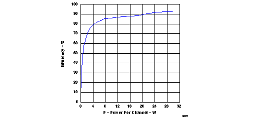
每通道效率与功耗对比

4 修订历史记录
| 日期 | 修订版本 | 注释 |
|---|---|---|
| 2016 年 12 月 | * | 最初发布。 |