ZHCSGH3A March 2016 – July 2017 TAS5782M
PRODUCTION DATA.
- 1 特性
- 2 应用
- 3 说明
- 4 修订历史记录
- 5 Device Comparison Table
- 6 Pin Configuration and Functions
-
7 Specifications
- 7.1 Absolute Maximum Ratings
- 7.2 ESD Ratings
- 7.3 Recommended Operating Conditions
- 7.4 Thermal Information
- 7.5 Electrical Characteristics
- 7.6 Power Dissipation Characteristics
- 7.7 MCLK Timing
- 7.8 Serial Audio Port Timing – Slave Mode
- 7.9 Serial Audio Port Timing – Master Mode
- 7.10 I2C Bus Timing – Standard
- 7.11 I2C Bus Timing – Fast
- 7.12 SPK_MUTE Timing
- 7.13 Typical Characteristics
- 8 Parametric Measurement Information
-
9 Detailed Description
- 9.1 Overview
- 9.2 Functional Block Diagram
- 9.3
Feature Description
- 9.3.1 Power-on-Reset (POR) Function
- 9.3.2 Device Clocking
- 9.3.3
Serial Audio Port
- 9.3.3.1 Clock Master Mode from Audio Rate Master Clock
- 9.3.3.2 Clock Master from a Non-Audio Rate Master Clock
- 9.3.3.3 Clock Slave Mode with 4-Wire Operation (SCLK, MCLK, LRCK/FS, SDIN)
- 9.3.3.4 Clock Slave Mode with SCLK PLL to Generate Internal Clocks (3-Wire PCM)
- 9.3.3.5 Serial Audio Port – Data Formats and Bit Depths
- 9.3.3.6 Input Signal Sensing (Power-Save Mode)
- 9.3.4 Enable Device
- 9.3.5 Volume Control
- 9.3.6 Adjustable Amplifier Gain and Switching Frequency Selection
- 9.3.7
Error Handling and Protection Suite
- 9.3.7.1 Device Overtemperature Protection
- 9.3.7.2 SPK_OUTxx Overcurrent Protection
- 9.3.7.3 DC Offset Protection
- 9.3.7.4 Internal VAVDD Undervoltage-Error Protection
- 9.3.7.5 Internal VPVDD Undervoltage-Error Protection
- 9.3.7.6 Internal VPVDD Overvoltage-Error Protection
- 9.3.7.7 External Undervoltage-Error Protection
- 9.3.7.8 Internal Clock Error Notification (CLKE)
- 9.3.8 GPIO Port and Hardware Control Pins
- 9.3.9 I2C Communication Port
- 9.4 Device Functional Modes
- 10Application and Implementation
- 11Power Supply Recommendations
- 12Layout
-
13Register Maps
- 13.1
Registers - Page 0
- 13.1.1 Register 1 (0x01)
- 13.1.2 Register 6 (0x06)
- 13.1.3 Register 7 (0x07)
- 13.1.4 Register 8 (0x08)
- 13.1.5 Register 9 (0x09)
- 13.1.6 Register 12 (0x0C)
- 13.1.7 Register 13 (0x0D)
- 13.1.8 Register 14 (0x0E)
- 13.1.9 Register 15 (0x0F)
- 13.1.10 Register 16 (0x10)
- 13.1.11 Register 17 (0x11)
- 13.1.12 Register 18 (0x12)
- 13.1.13 Register 20 (0x14)
- 13.1.14 Register 21 (0x15)
- 13.1.15 Register 22 (0x16)
- 13.1.16 Register 23 (0x17)
- 13.1.17 Register 24 (0x18)
- 13.1.18 Register 27 (0x1B)
- 13.1.19 Register 28 (0x1C)
- 13.1.20 Register 29 (0x1D)
- 13.1.21 Register 30 (0x1E)
- 13.1.22 Register 32 (0x20)
- 13.1.23 Register 33 (0x21)
- 13.1.24 Register 34 (0x22)
- 13.1.25 Register 37 (0x25)
- 13.1.26 Register 40 (0x28)
- 13.1.27 Register 41 (0x29)
- 13.1.28 Register 42 (0x2A)
- 13.1.29 Register 43 (0x2B)
- 13.1.30 Register 44 (0x2C)
- 13.1.31 Register 59 (0x3B)
- 13.1.32 Register 60 (0x3C)
- 13.1.33 Register 61 (0x3D)
- 13.1.34 Register 62 (0x3E)
- 13.1.35 Register 63 (0x3F)
- 13.1.36 Register 64 (0x40)
- 13.1.37 Register 65 (0x41)
- 13.1.38 Register 67 (0x43)
- 13.1.39 Register 68 (0x44)
- 13.1.40 Register 69 (0x45)
- 13.1.41 Register 70 (0x46)
- 13.1.42 Register 71 (0x47)
- 13.1.43 Register 72 (0x48)
- 13.1.44 Register 73 (0x49)
- 13.1.45 Register 74 (0x4A)
- 13.1.46 Register 75 (0x4B)
- 13.1.47 Register 76 (0x4C)
- 13.1.48 Register 78 (0x4E)
- 13.1.49 Register 79 (0x4F)
- 13.1.50 Register 83 (0x53)
- 13.1.51 Register 85 (0x55)
- 13.1.52 Register 86 (0x56)
- 13.1.53 Register 87 (0x57)
- 13.1.54 Register 88 (0x58)
- 13.1.55 Register 91 (0x5B)
- 13.1.56 Register 92 (0x5C)
- 13.1.57 Register 93 (0x5D)
- 13.1.58 Register 94 (0x5E)
- 13.1.59 Register 95 (0x5F)
- 13.1.60 Register 108 (0x6C)
- 13.1.61 Register 119 (0x77)
- 13.1.62 Register 120 (0x78)
- 13.2 Registers - Page 1
- 13.1
Registers - Page 0
- 14器件和文档支持
- 15机械、封装和可订购信息
9.3.3.2 Clock Master from a Non-Audio Rate Master Clock
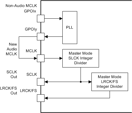
The classic example here is running a 96-kHz sampling system. Given the clock tree for the device (shown in Figure 65), a non-audio clock rate cannot be brought into the MCLK to the PLL in master mode. Therefore, the PLL source must be configured to be a GPIO pin, and the output brought back into another GPIO pin.
 Figure 67. Generating Audio Clocks Using Non-Audio Clock Sources
The clock flow through the system is shown in Figure 67. The newly generated MCLK must be brought out of the device on a GPIO pin, then brought into the MCLK pin for integer division to create SCLK and LRCK/FS outputs.
NOTE
Pull-up resistors should be used on SCLK and LRCK/FS in master mode to ensure the device remains out of sleep mode.