ZHCSFZ6 December 2016 TAS6422-Q1
PRODUCTION DATA.
- 1 特性
- 2 应用
- 3 说明
- 4 修订历史记录
- 5 说明(续)
- 6 Device Comparison Table
- 7 Pin Configuration and Functions
- 8 Specifications
- 9 Parameter measurement Information
-
10Detailed description
- 10.1 Overview
- 10.2 Functional Block Diagram
- 10.3
Feature Description
- 10.3.1 Serial Audio Port
- 10.3.2 High-Pass Filter
- 10.3.3 Volume Control and Gain
- 10.3.4 High-Frequency Pulse-Width Modulator (PWM)
- 10.3.5 Gate Drive
- 10.3.6 Power FETs
- 10.3.7 Load Diagnostics
- 10.3.8
Protection and Monitoring
- 10.3.8.1 Overcurrent Limit (ILIMIT)
- 10.3.8.2 Overcurrent Shutdown (ISD)
- 10.3.8.3 DC Detect
- 10.3.8.4 Clip Detect
- 10.3.8.5 Global Overtemperature Warning (OTW), Overtemperature Shutdown (OTSD)
- 10.3.8.6 Channel Overtemperature Warning [OTW(i)] and Shutdown [OTSD(i)]
- 10.3.8.7 Undervoltage (UV) and Power-On-Reset (POR)
- 10.3.8.8 Overvoltage (OV) and Load Dump
- 10.3.9 Power Supply
- 10.3.10 Hardware Control Pins
- 10.4 Device Functional Modes
- 10.5 Programming
- 10.6
Register Maps
- 10.6.1 Mode Control Register (address = 0x00) [default = 0x00]
- 10.6.2 Miscellaneous Control 1 Register (address = 0x01) [default = 0x32]
- 10.6.3 Miscellaneous Control 2 Register (address = 0x02) [default = 0x62]
- 10.6.4 SAP Control (Serial Audio-Port Control) Register (address = 0x03) [default = 0x04]
- 10.6.5 Channel State Control Register (address = 0x04) [default = 0x55]
- 10.6.6 Channel 1 Through 2 Volume Control Registers (address = 0x05-0x06) [default = 0xCF]
- 10.6.7 DC Load Diagnostic Control 1 Register (address = 0x09) [default = 0x00]
- 10.6.8 DC Load Diagnostic Control 2 Register (address = 0x0A) [default = 0x11]
- 10.6.9 DC Load Diagnostic Report 1 Register (address = 0x0C) [default = 0x00]
- 10.6.10 DC Load Diagnostics Report 3 Line Output Register (address = 0x0E) [default = 0x00]
- 10.6.11 Channel State Reporting Register (address = 0x0F) [default = 0x55]
- 10.6.12 Channel Faults (Overcurrent, DC Detection) Register (address = 0x10) [default = 0x00]
- 10.6.13 Global Faults 1 Register (address = 0x11) [default = 0x00]
- 10.6.14 Global Faults 2 Register (address = 0x12) [default = 0x00]
- 10.6.15 Warnings Register (address = 0x13) [default = 0x20]
- 10.6.16 Pin Control Register (address = 0x14) [default = 0x00]
- 10.6.17 AC Load Diagnostic Control 1 Register (address = 0x15) [default = 0x00]
- 10.6.18 AC Load Diagnostic Control 2 Register (address = 0x16) [default = 0x00]
- 10.6.19 AC Load Diagnostic Impedance Report Ch1 through CH2 Registers (address = 0x17-0x18) [default = 0x00]
- 10.6.20 AC Load Diagnostic Phase Report High Register (address = 0x1B) [default = 0x00]
- 10.6.21 AC Load Diagnostic Phase Report Low Register (address = 0x1C) [default = 0x00]
- 10.6.22 AC Load Diagnostic STI Report High Register (address = 0x1D) [default = 0x00]
- 10.6.23 AC Load Diagnostic STI Report Low Register (address = 0x1E) [default = 0x00]
- 10.6.24 Miscellaneous Control 3 Register (address = 0x21) [default = 0x00]
- 10.6.25 Clip Control Register (address = 0x22) [default = 0x01]
- 10.6.26 Clip Window Register (address = 0x23) [default = 0x14]
- 10.6.27 Clip Warning Register (address = 0x24) [default = 0x00]
- 10.6.28 ILIMIT Status Register (address = 0x25) [default = 0x00]
- 10.6.29 Miscellaneous Control 4 Register (address = 0x26) [default = 0x40]
- 11Application and Implementation
- 12Power Supply Recommendations
- 13Layout
- 14器件和文档支持
- 15机械、封装和可订购信息
1 特性
- 符合汽车应用 标准
- 音频输入
- 2 通道 I2S 或 4/8 通道 TDM 输入
- 输入采样率:44.1kHz、48kHz、96kHz
- 输入格式:16 位至 32 位 I2S 和 TDM
- 音频输出
- 2 通道桥接负载 (BTL),可选并行桥接负载 (PBTL)
- 高达 2.1MHz 的输出开关频率
- 在 4Ω 负载、25V 电源电压和 10% THD 的条件下,输出功率为 75W
- 在 2Ω 负载、14.4V 电源电压和 10% THD 的条件下,输出功率为 45W
- 在 2Ω 负载、25V PBTL 和 10% THD 的条件下,输出功率为 150W
- 在 4Ω 负载和 14.4V 电源电压条件下的音频性能
- 输出功率为 1W 时的总谐波失真 + 噪声 (THD+N) < 0.03%
- 42µVRMS 输出噪声
- –90dB 串扰
- 负载诊断功能
- 输出负载开路和短路
- 输出至电池短路或接地短路
- 线路输出检测高达 6kΩ
- 无输入时钟时也可运行
- 用于高频扬声器检测的交流诊断功能
- 保护
- 输出限流
- 输出短路保护
- 40V 负载突降
- 可承受接地开路和电源开路
- 直流偏移
- 过热
- 欠压和过压
- 常规运行
- 评估模块 (EVM) 通过 CISPR25-L5 电磁兼容性 (EMC) 规范
- 4.5V 至 26.4V 电源电压
- I2C 控制具有 4 个地址选项
- 削波检测和热警告
2 应用
- 汽车音响主机
- 汽车外部放大器模块
3 说明
TAS6422-Q1 器件是一款 2 通道数字输入 D 类音频放大器,专为汽车音响主机和外部放大器模块而设计。在 14.4V 电源电压条件下,当负载为 4Ω、THD+N 为 10% 时,该器件可提供 2 通道的 27W 输出功率;当负载为 2Ω、THD+N 为 10% 时,该器件可提供 45W 的输出功率。在 25V 电源电压条件下,当负载为 4Ω、THD+N 为 10% 时,该器件可提供 75W 的输出功率。与传统的线性放大器解决方案相比,D 类拓扑技术显著提高了器件效率。输出开关频率既可以设置为高于调幅 (AM) 频带,以消除 AM 频带干扰并降低输出滤波需求及成本;也可以设置为低于 AM 频带,以优化器件效率。
4.5V 至 26.4V 的宽电源电压范围有助于将启停 应用中的音频失真降至最低程度。
器件信息(1)
| 器件型号 | 封装 | 封装尺寸(标称值) |
|---|---|---|
| TAS6422-Q1 | HSSOP (56) | 18.41mm × 7.49mm |
- 如需了解所有可用封装,请参阅米6体育平台手机版_好二三四说明书末尾的可订购米6体育平台手机版_好二三四附录。
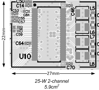
PCB 区域

4 修订历史记录
| 日期 | 修订版本 | 注释 |
|---|---|---|
| 2016 年 12 月 | * | 初始发行版。 |