ZHCSJB8 February 2019 TAS6424M-Q1
PRODUCTION DATA.
- 1 特性
- 2 应用
- 3 说明
- 4 修订历史记录
- 5 说明(续)
- 6 Device Options
- 7 Pin Configuration and Functions
- 8 Specifications
- 9 Parameter Measurement Information
-
10Detailed Description
- 10.1 Overview
- 10.2 Functional Block Diagram
- 10.3
Feature Description
- 10.3.1 Serial Audio Port
- 10.3.2 High-Pass Filter
- 10.3.3 Volume Control and Gain
- 10.3.4 High-Frequency Pulse-Width Modulator (PWM)
- 10.3.5 Gate Drive
- 10.3.6 Power FETs
- 10.3.7 Load Diagnostics
- 10.3.8
Protection and Monitoring
- 10.3.8.1 Overcurrent Limit (ILIMIT)
- 10.3.8.2 Overcurrent Shutdown (ISD)
- 10.3.8.3 DC Detect
- 10.3.8.4 Clip Detect
- 10.3.8.5 Global Overtemperature Warning (OTW), Overtemperature Shutdown (OTSD)
- 10.3.8.6 Channel Overtemperature Warning [OTW(i)] and Shutdown [OTSD(i)]
- 10.3.8.7 Undervoltage (UV) and Power-On-Reset (POR)
- 10.3.8.8 Overvoltage (OV) and Load Dump
- 10.3.9 Power Supply
- 10.3.10 Hardware Control Pins
- 10.4 Device Functional Modes
- 10.5 Programming
- 10.6
Register Maps
- 10.6.1 Mode Control Register (address = 0x00) [default = 0x00]
- 10.6.2 Miscellaneous Control 1 Register (address = 0x01) [default = 0x32]
- 10.6.3 Miscellaneous Control 2 Register (address = 0x02) [default = 0x62]
- 10.6.4 SAP Control (Serial Audio-Port Control) Register (address = 0x03) [default = 0x04]
- 10.6.5 Channel State Control Register (address = 0x04) [default = 0x55]
- 10.6.6 Channel 1 Through 4 Volume Control Registers (address = 0x05–0x08) [default = 0xCF]
- 10.6.7 DC Load Diagnostic Control 1 Register (address = 0x09) [default = 0x00]
- 10.6.8 DC Load Diagnostic Control 2 Register (address = 0x0A) [default = 0x11]
- 10.6.9 DC Load Diagnostic Control 3 Register (address = 0x0B) [default = 0x11]
- 10.6.10 DC Load Diagnostic Report 1 Register (address = 0x0C) [default = 0x00]
- 10.6.11 DC Load Diagnostic Report 2 Register (address = 0x0D) [default = 0x00]
- 10.6.12 DC Load Diagnostics Report 3 Line Output Register (address = 0x0E) [default = 0x00]
- 10.6.13 Channel State Reporting Register (address = 0x0F) [default = 0x55]
- 10.6.14 Channel Faults (Overcurrent, DC Detection) Register (address = 0x10) [default = 0x00]
- 10.6.15 Global Faults 1 Register (address = 0x11) [default = 0x00]
- 10.6.16 Global Faults 2 Register (address = 0x12) [default = 0x00]
- 10.6.17 Warnings Register (address = 0x13) [default = 0x20]
- 10.6.18 Pin Control Register (address = 0x14) [default = 0x00]
- 10.6.19 AC Load Diagnostic Control 1 Register (address = 0x15) [default = 0x00]
- 10.6.20 AC Load Diagnostic Control 2 Register (address = 0x16) [default = 0x00]
- 10.6.21 AC Load Diagnostic Impedance Report Ch1 through CH4 Registers (address = 0x17–0x1A) [default = 0x00]
- 10.6.22 AC Load Diagnostic Phase Report High Register (address = 0x1B) [default = 0x00]
- 10.6.23 AC Load Diagnostic Phase Report Low Register (address = 0x1C) [default = 0x00]
- 10.6.24 AC Load Diagnostic STI Report High Register (address = 0x1D) [default = 0x00]
- 10.6.25 AC Load Diagnostic STI Report Low Register (address = 0x1E) [default = 0x00]
- 10.6.26 Miscellaneous Control 3 Register (address = 0x21) [default = 0x00]
- 10.6.27 Clip Control Register (address = 0x22) [default = 0x01]
- 10.6.28 Clip Window Register (address = 0x23) [default = 0x14]
- 10.6.29 Clip Warning Register (address = 0x24) [default = 0x00]
- 10.6.30 ILIMIT Status Register (address = 0x25) [default = 0x00]
- 10.6.31 Miscellaneous Control 4 Register (address = 0x26) [default = 0x40]
- 11Application and Implementation
- 12Power Supply Recommendations
- 13Layout
- 14器件和文档支持
- 15机械、封装和可订购信息
10.3.9.1 Vehicle-Battery Power-Supply Sequence
Power-Up Sequence
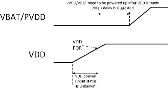
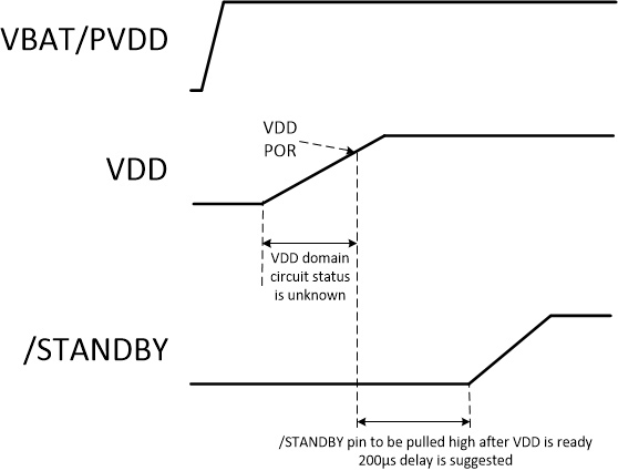
In a typical system, the VBAT and PVDD supplies are both connected to the vehicle battery and power up at the same time. The VDD supply is recommended to be applied 200µs before the VBAT and PVDD supplies start ramping to their recommended operating range. As reference, please see Figure 39. If this is unfeasible and VBAT / PVDD will be supplied before VDD, it is recommended wait 200µs after VDD is supplied before pulling the STANDBY pin high. As reference, please see Figure 40.
 Figure 39. Power-Up Sequence Option 1
  Figure 40. Power-Up Sequence Option 2
 Power-Down Sequence
When removing power from the device, TI recommends to deassert the VBAT and PVDD supplies together first, which provides the lowest click and pop performance, and VDD last. During powering down, VDD must remain available for at least 1.01s after all output stages got set to Hi-Z. To shorten this required delay to 46ms, a 20kOhm parallel resistor between AVDD and AVSS can be added.