ZHCSCR9C
September 2014 – February 2017
TCA9534A
PRODUCTION DATA.
1
特性
2
应用
3
说明
Device Images
简化的原理图
4
修订历史记录
5
Pin Configuration and Functions
6
Specifications
6.1
Absolute Maximum Ratings
6.2
Handling Ratings
6.3
Recommended Operating Conditions
6.4
Thermal Information
6.5
Electrical Characteristics
6.6
I2C Interface Timing Requirements
6.7
Switching Characteristics
6.8
Typical Characteristics
7
Parameter Measurement Information
8
Detailed Description
8.1
Overview
8.2
Functional Block Diagram
8.3
Feature Description
8.3.1
I/O Port
8.3.2
Interrupt Output (INT)
8.4
Device Functional Modes
8.4.1
Power-On Reset
8.5
Programming
8.5.1
I2C Interface
8.6
Register Maps
8.6.1
Device Address
8.6.2
Control Register and Command Byte
8.6.3
Register Descriptions
8.6.3.1
Bus Transactions
8.6.3.1.1
Writes
8.6.3.1.2
Reads
9
Application and Implementation
9.1
Application Information
9.2
Typical Application
9.2.1
Design Requirements
9.2.1.1
Calculating Junction Temperature and Power Dissipation
9.2.1.2
Minimizing ICC When I/Os Control LEDs
9.2.2
Detailed Design Procedure
9.2.3
Application Curves
10
Power Supply Recommendations
10.1
Power-On Reset Requirements
11
Layout
11.1
Layout Guidelines
11.2
Layout Example
12
器件和文档支持
12.1
相关文档
12.2
接收文档更新通知
12.3
社区资源
12.4
商标
12.5
静电放电警告
12.6
Glossary
13
机械、封装和可订购信息
封装选项
机械数据 (封装 | 引脚)
DW|16
MSOI003I
PW|16
MPDS361A
散热焊盘机械数据 (封装 | 引脚)
DW|16
QFND313D
订购信息
zhcscr9c_oa
zhcscr9c_pm
7
Parameter Measurement Information
A.
C
L
includes probe and jig capacitance.
B.
All inputs are supplied by generators having the following characteristics: PRR ≤ 10 MHz, Z
O
= 50 Ω, t
r
/t
f
≤ 30 ns.
C.
All parameters and waveforms are not applicable to all devices.
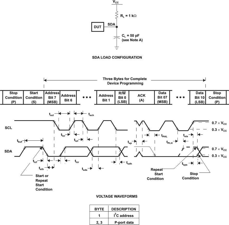
Figure 19.
I
2
C Interface Load Circuit and Voltage Waveforms
A.
C
L
includes probe and jig capacitance.
B.
All inputs are supplied by generators having the following characteristics: PRR ≤ 10 MHz, Z
O
= 50 Ω, t
r
/t
f
≤ 30 ns.
C.
All parameters and waveforms are not applicable to all devices.
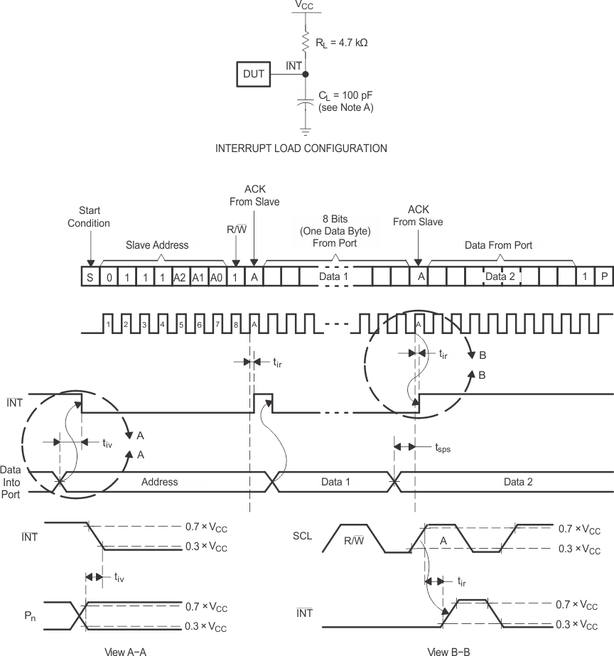
Figure 20.
Interrupt Load Circuit and Voltage Waveforms
A.
C
L
includes probe and jig capacitance.
B.
t
pv
is measured from 0.7 × V
CC
on SCL to 50% I/O (Pn) output.
C.
All inputs are supplied by generators having the following characteristics: PRR ≤ 10 MHz, Z
O
= 50 Ω, t
r
/t
f
≤ 30 ns.
D.
The outputs are measured one at a time, with one transition per measurement.
E.
All parameters and waveforms are not applicable to all devices.
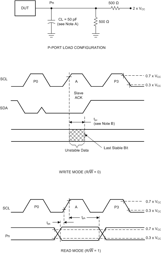
Figure 21.
P-Port Load Circuit and Voltage Waveforms
千亿体育app官网登录(中国)官方网站IOS/安卓通用版/手机APP
|
米乐app下载官网(中国)|ios|Android/通用版APP最新版
|
米乐|米乐·M6(中国大陆)官方网站
|
千亿体育登陆地址
|
华体会体育(中国)HTH·官方网站
|
千赢qy国际_全站最新版千赢qy国际V6.2.14安卓/IOS下载
|
18新利网v1.2.5|中国官方网站
|
bob电竞真人(中国官网)安卓/ios苹果/电脑版【1.97.95版下载】
|
千亿体育app官方下载(中国)官方网站IOS/安卓/手机APP下载安装
|