SLVS220G July 1999 – August 2016 TL7700
PRODUCTION DATA.
- 1 Features
- 2 Applications
- 3 Description
- 4 Revision History
- 5 Pin Configuration and Functions
- 6 Specifications
- 7 Parameter Measurement Information
- 8 Detailed Description
- 9 Application and Implementation
- 10Power Supply Recommendations
- 11Layout
- 12Device and Documentation Support
- 13Mechanical, Packaging, and Orderable Information
封装选项
机械数据 (封装 | 引脚)
散热焊盘机械数据 (封装 | 引脚)
- PS|8
订购信息
9 Application and Implementation
NOTE
Information in the following applications sections is not part of the TI component specification, and TI does not warrant its accuracy or completeness. TI’s customers are responsible for determining suitability of components for their purposes. Customers should validate and test their design implementation to confirm system functionality.
9.1 Application Information
The TL7700 supply-voltage supervisor allows for any voltage greater than 500mV to be monitored. This flexibility allows it to be used in many applications from FPGAs and Microcontrollers to Industrial supply monitoring.
9.2 Typical Application
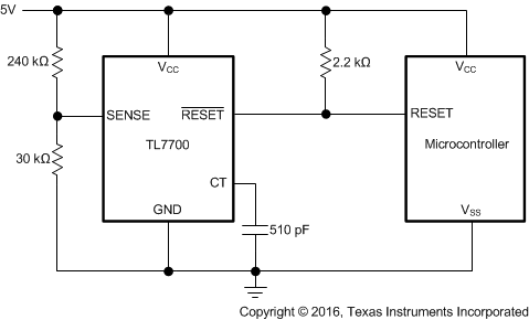
Figure 21 shows an application where the TL7700 device is being used to sense the voltage supply for a microcontroller that is supplied with 5 V. If the sense voltage drops below 4.5 V, the RESET pin is pulled LOW, signaling the microcontroller to reset.
 Figure 21. 5-V Supply Voltage Supervision
9.2.1 Design Requirements
- When the TL7700 is used for system power-on reset, the output pulse duration, tpo, must be set longer than the power rise time. The value of tpo is: tpo = Ct × 105 seconds
- The RESET output is an open-collector output, so a pullup resistor is required.
9.2.2 Detailed Design Procedure
The SENSE terminal input voltage, Vs, of the TL7700 typically is 500 mV. By using two external resistors, any sense voltage over 500 mV can be sensed.
Resistor R1 should be selected first to set the desired hysteresis. See Sense-Voltage Hysteresis Setting for detailed information on how to set the hysteresis.
Resistor R2 should then be selected based on the R1 value and the desired Vs' voltage. In Figure 18, the sensing voltage, Vs', is calculated as: Vs' = Vs × (R1 + R2)/R2
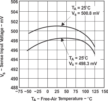
9.2.3 Application Curve
