ZHCSIO0A December   2017  – August 2018 TLC6C5724-Q1

PRODUCTION DATA.  

  1. 特性
  2. 应用
  3. 说明
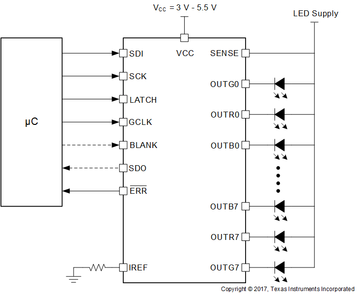
    1.     典型应用原理图
  4. 修订历史记录
  5. Pin Configuration and Functions
    1.     Pin Functions
  6. Specifications
    1. 6.1 Absolute Maximum Ratings
    2. 6.2 ESD Ratings
    3. 6.3 Recommended Operating Conditions
    4. 6.4 Thermal Information
    5. 6.5 Electrical Characteristics
    6. 6.6 Timing Requirements
    7. 6.7 Switching Characteristics
    8. 6.8 Typical Characteristics
  7. Detailed Description
    1. 7.1 Overview
    2. 7.2 Functional Block Diagram
    3. 7.3 Feature Description
      1. 7.3.1 Maximum Constant-Sink-Current Setting
      2. 7.3.2 Brightness Control and Dot Correction
      3. 7.3.3 Grayscale Configuration
        1. 7.3.3.1 PWM Auto Repeat
        2. 7.3.3.2 PWM Timing Reset
      4. 7.3.4 Diagnostics
        1. 7.3.4.1  LED Diagnostics
        2. 7.3.4.2  Adjacent-Pin-Short Check
        3. 7.3.4.3  IREF Short and IREF Open Detection
        4. 7.3.4.4  Pre-Thermal Warning Flag
        5. 7.3.4.5  Thermal Error Flag
        6. 7.3.4.6  Negate Bit Toggle
        7. 7.3.4.7  LOD_LSD Self-Test
        8. 7.3.4.8  ERR Pin
        9. 7.3.4.9  ERROR Clear
        10. 7.3.4.10 Global Reset
        11. 7.3.4.11 Slew Rate Control
        12. 7.3.4.12 Channel Group Delay
    4. 7.4 Device Functional Modes
      1. 7.4.1 Power Up
      2. 7.4.2 Device Initialization
      3. 7.4.3 Fault Mode
      4. 7.4.4 Normal Operation
    5. 7.5 Programming
      1. 7.5.1 Register Write and Read
        1. 7.5.1.1 FC-BC-DC Write
          1. 7.5.1.1.1 FC Data Write
          2. 7.5.1.1.2 BC Data Write
          3. 7.5.1.1.3 DC Data Write
        2. 7.5.1.2 Grayscale Data Write
        3. 7.5.1.3 Special Command Function
          1. 7.5.1.3.1 GS Read
          2. 7.5.1.3.2 FC-BC-DC Read
          3. 7.5.1.3.3 Status Information Data Read
    6. 7.6 Register Maps
      1. 7.6.1 GRAYSCALE Registers
        1. 7.6.1.1 OUTn_GS Register (Offset = 0h)
          1. Table 25. OUTn_GS Register Field Descriptions
      2. 7.6.2 FC-BC-DC Registers
        1. 7.6.2.1 FC-BC-DC Register (Offset = 1h)
          1. Table 28. FC-BC-DC Register Field Descriptions
      3. 7.6.3 SID Registers
        1. 7.6.3.1 SID Register (Offset = 2h)
          1. Table 31. SID Register Field Descriptions
  8. Application and Implementation
    1. 8.1 Application Information
    2. 8.2 Typical Application
      1. 8.2.1 Design Requirements
      2. 8.2.2 Detailed Design Procedure
      3. 8.2.3 Application Curves
  9. Power Supply Recommendations
  10. 10Layout
    1. 10.1 Layout Guidelines
    2. 10.2 Layout Example
  11. 11器件和文档支持
    1. 11.1 接收文档更新通知
    2. 11.2 社区资源
    3. 11.3 商标
    4. 11.4 静电放电警告
    5. 11.5 术语表
  12. 12机械、封装和可订购信息

封装选项

机械数据 (封装 | 引脚)
散热焊盘机械数据 (封装 | 引脚)
订购信息

说明

有一些 适用于 指示灯和 LCD 局部调光背光照明的汽车应用。对于此类 应用,,多数人认为需要使用多通道恒定电流 LED 驱动器。要求获取相同的强度和 LED 色温。为确保系统级安全起见,LED 驱动器必须能够检测故障。

TLC6C5724-Q1 器件是一款车用 24 通道恒定电流 RGB LED 驱动器,可利用该器件在该 LED 上进行测试。TLC6C5724-Q1 器件可提供最高 50mA 的输出电流(由外部电阻器设定)。该器件具有 7 位点校正功能,每路输出 2 个范围。该器件还针对每个颜色组的输出提供 8 位强度控制功能。可通过 12 位、10 位或 8 位灰度控制调整每个输出的强度。该器件的电路能够检测各种系统故障,其中包括 LED 故障、邻近引脚短路故障、基准电阻器故障等。压摆率控制具有 2 个可调节位置,可最大限度地降低系统噪声。输出电平从一个 LED 组变到另一个 LED 组时有一段时间间隔。此间隔有助于减小启动电流。SDI 和 SDO 引脚允许串联多个器件,并通过一个串行接口控制。

器件信息(1)

器件型号 封装 封装尺寸(标称值)
TLC6C5724-Q1 HTSSOP (38) 6.20mm x 12.50mm
  1. 如需了解所有可用封装,请参阅数据表末尾的可订购米6体育平台手机版_好二三四附录。

典型应用原理图
TLC6C5724-Q1 typical-applicaiton-schematic-01-slasek2.gif